
Filter type thin film pressure reducing valve

A filter type, pressure reducing valve technology, applied in safety valves, balance valves, valve devices, etc., can solve the problems of large medium flow resistance, difficult valve body processing, and difficult positioning of filter nets, so as to achieve convenient positioning and use, reduce The difficulty of production and processing, the effect of simplifying the internal structure

Active Publication Date: 2014-01-29
ZHEJIANG DUNAN INTELLIGENT CONTROL TECH CO LTD
View PDF5 Cites 0 Cited by
  • Summary
  • Abstract
  • Description
  • Claims
  • Application Information

AI Technical Summary

Problems solved by technology

[0010] The purpose of the present invention is to provide a filter-type membrane pressure reducing valve, which can effectively solve the problems of the existing filter-type membrane pressure-relief valve with too many turns, large medium flow resistance, and difficult positioning of the filter net, which lead to difficult processing of the valve body.

Method used


Image

  • Filter type thin film pressure reducing valve
  • Filter type thin film pressure reducing valve
  • Filter type thin film pressure reducing valve

Examples


Embodiment Construction

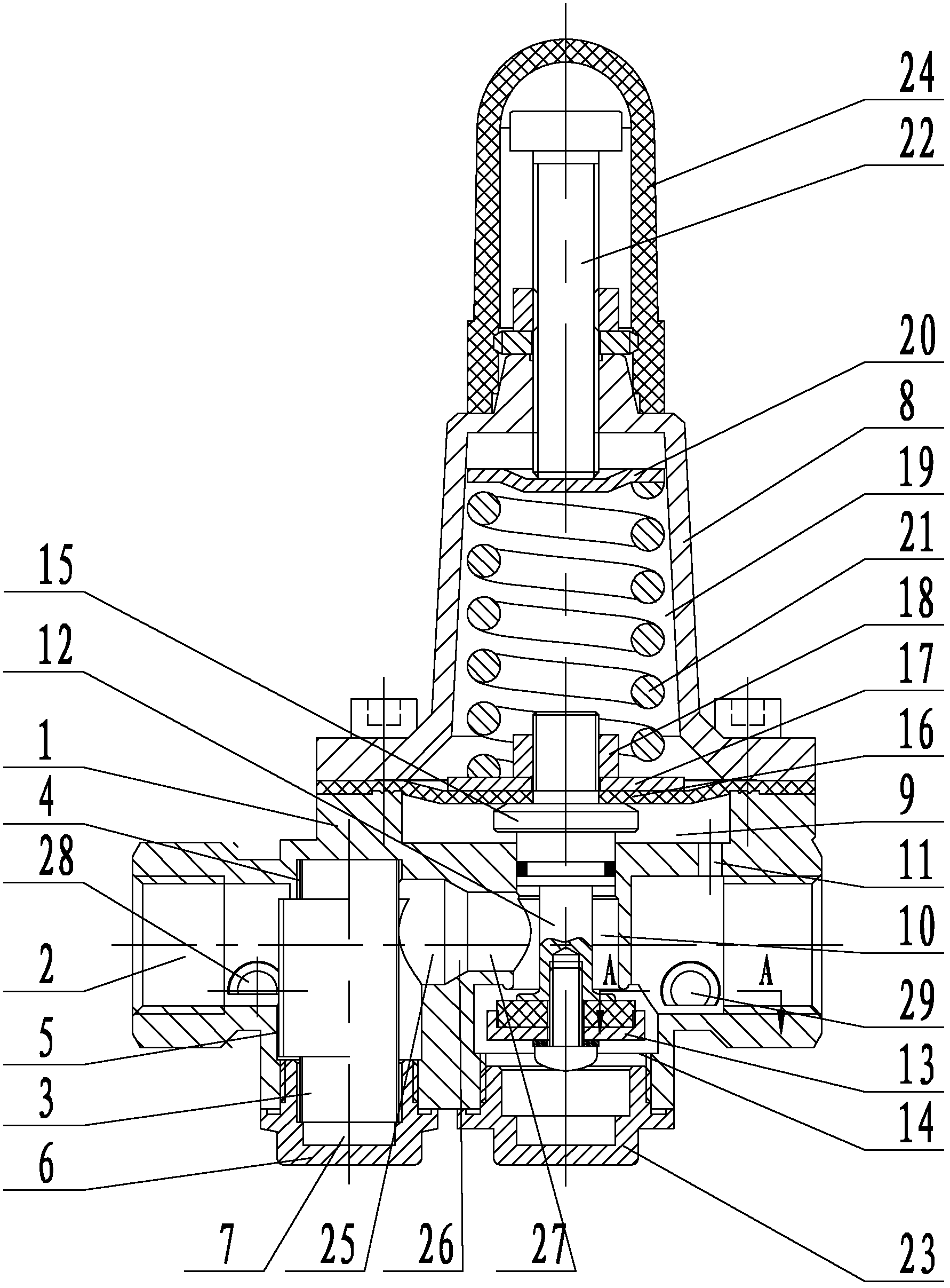
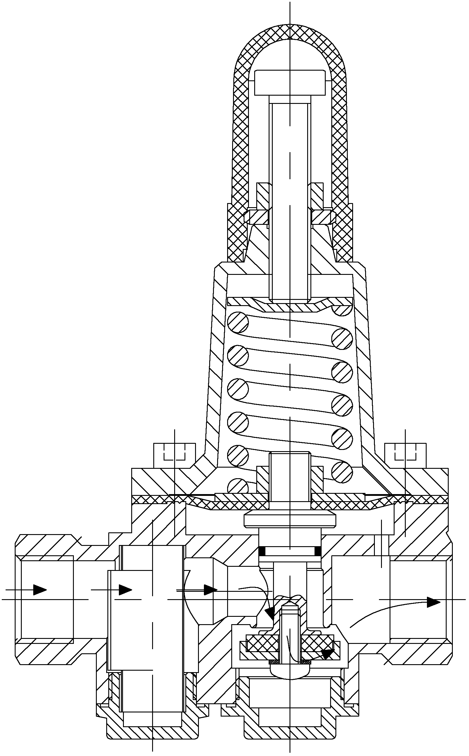
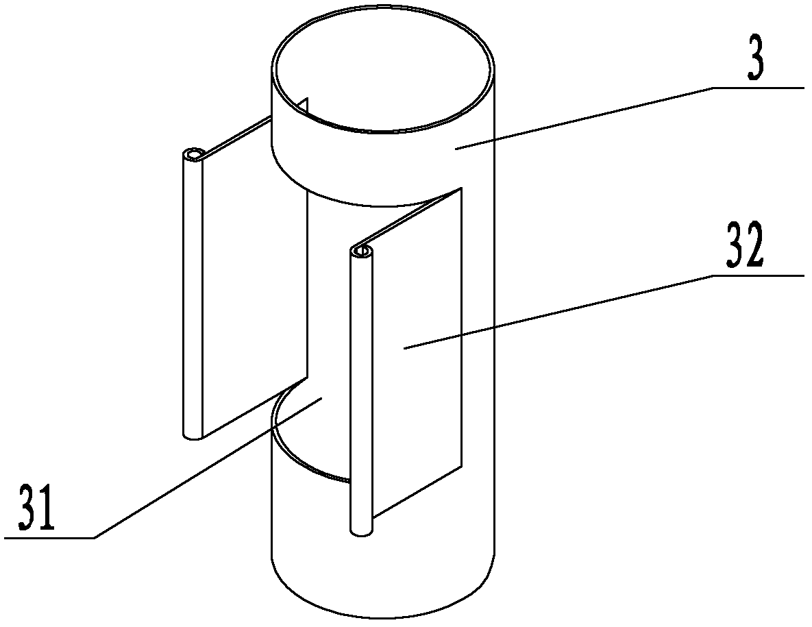
[0026] refer to figure 1 It is an embodiment of the filter type membrane pressure reducing valve of the present invention. The filter type membrane pressure reducing valve includes a valve body 1, a pressure reducing device, and a filter device. A water flow channel 2 is opened in the valve body 1. The filter device and the pressure reducing device The pressure devices are all arranged in the valve body 1, the filter device is arranged between the decompression device and the water inlet of the water flow channel, the filter device includes a filter screen 3, the filter screen 3 is cylindrical, and the filter screen 3 There is a notch 31 on the side wall of the middle part, the two vertical sides of the notch 31 are provided with fixing parts 32, and the first placement hole 4 is opened in the valve body 1, and the first placement hole 4 is connected with the water flow channel. 2, the side where the first placement hole 4 intersects with the water flow channel 2 is provided ...


PUM


Abstract

The invention discloses a filter type thin film pressure reducing valve, which comprises a valve body, a pressure reducing device and a filter device, wherein a water flow passage is formed in the valve body; both the filter device and the pressure reducing device are arranged in the valve body; the filter device is arranged on the upstream of the pressure reducing device and comprises a filtering net; the filtering net is columnar; the side wall of the middle part of the filtering net is provided with a notch; two vertical side edges of the notch are provided with fixing parts; a first placement hole is formed in the valve body and is communicated with the water flow passage; the side of the first placement hole which is crossed with the water flow passage is provided with a fixing groove which is matched with the fixing part; and the filtering net is arranged in the first placement hole. The valve has the advantages that: a flow path for a medium is changed from an inverted S shape into a through type during filtration by the filtering net structure; the reduction of flow resistance is realized; an internal structure is simplified; the filtering net is more convenient to position and use; and the production difficulty of the valve body is greatly reduced.

Description

technical field [0001] The invention relates to a filter type membrane pressure reducing valve. Background technique [0002] Such as Figure 5 As shown, in the existing products, there is known a filter type membrane pressure reducing valve, which is mainly composed of valve body, valve cover, valve stem, diaphragm, spring, valve disc, filter screen, end cap and other parts. Among them, the valve body is the main part of the product, and its filter structure is set at the front end of the pressure reducing valve, and the installation position of the filter screen is below the center line of the valve body in the horizontal direction; the filter screen is a cylindrical structure, and the upper and lower bottom surfaces penetrate; The installation method is to install it vertically from the bottom, and set a water hole in the horizontal direction of the valve body. The size of the water hole is smaller than the diameter of the filter screen, so that the filter screen will blo...

Claims


Application Information

Patent Timeline
Patent Type & Authority Patents(China)
IPC IPC(8): F16K17/22F16K51/00
Inventor 周云兵
Owner ZHEJIANG DUNAN INTELLIGENT CONTROL TECH CO LTD
Learn More