
Pipe drawing and crimping integrated machine for pipeline connection and use method of pipe drawing and crimping integrated machine

An all-in-one machine and pipeline technology, applied in metal processing, metal processing equipment, manufacturing tools, etc., can solve the problems of flange connection, pipe movement, and inconvenient connection, etc., so as to reduce the difficulty of installation and expand the application field , the effect of easy operation

Inactive Publication Date: 2012-05-02
李志雄
View PDF8 Cites 5 Cited by
  • Summary
  • Abstract
  • Description
  • Claims
  • Application Information

AI Technical Summary

Problems solved by technology

However, despite this, in fact, for the connection of long and bulky larger diameter RTP pipes, the flange connection is difficult to fit tightly, and it takes a lot of manpower to pull the two ends of the pipe into alignment, which is inconvenient to operate. One-piece pipe fittings more obvious
For the connection of buried pipelines, considering the difficulty of moving the pipes, the existing technology is to keep the pipes still, and rely on special equipment to move the heavy crimping machine to the pipes in the air, making the connection extremely inconvenient

Method used


Image

  • Pipe drawing and crimping integrated machine for pipeline connection and use method of pipe drawing and crimping integrated machine
  • Pipe drawing and crimping integrated machine for pipeline connection and use method of pipe drawing and crimping integrated machine
  • Pipe drawing and crimping integrated machine for pipeline connection and use method of pipe drawing and crimping integrated machine

Examples


Embodiment Construction

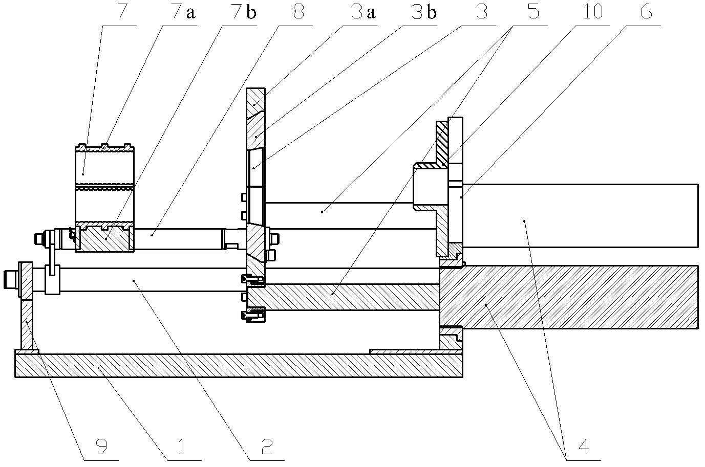
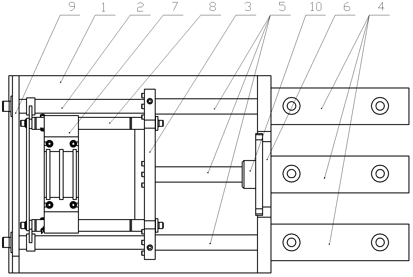
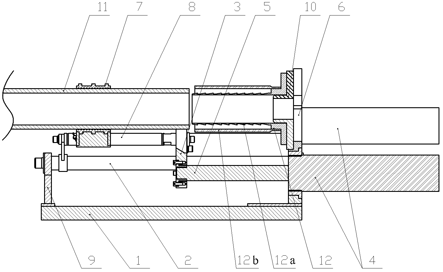
[0038] Figure 1 to Figure 6 Shown is an embodiment of a pipe-drawing and crimping integrated machine for pipe connection according to the present invention, such as figure 1 and figure 2 As shown, it includes a base 1, a guide column 2, a crimping moving plate 3, a hydraulic cylinder 4, a hydraulic moving bar 5, a pipe fixing plate 6, a pipe fixing piece 7, and a connecting rod 8.

[0039]There are two guide posts 2, and they are arranged on the base 1 in parallel through the guide post fixing plate 9 and the pipe fitting fixing plate 6. The guide post fixing plate 9 and the pipe fitting fixing plate 6 are provided with reinforcing ribs to enhance the pulling and crimping operations time tolerance. The crimping moving plate 3 is slidably arranged on the guide column 2 and connected with the hydraulic cylinder 4 through a hydraulic moving bar 5 . The crimping mobile plate 3 is composed of a moving seat 3a and a crimping die 3b, wherein the moving seat 3a is slidably arrang...


PUM


Abstract

The invention discloses a pipe drawing and crimping integrated machine for pipeline connection, comprising a base, at least two guide pillars, a crimping shifting plate, a hydraulic cylinder, a hydraulic shifting lever, a pipe fitting fixing plate, a pipe material fixing piece and a connecting rod, wherein the at least two guide pillars are arranged on the base in parallel; the crimping shifting plate is slidably arranged on the guide pillars and is connected with the hydraulic cylinder through the hydraulic shifting lever; the inner wall of the hydraulic shifting lever is in a shape of slant surface, and the pipe fitting fixing plate is located on one side of the crimping shifting plate; the connecting rod is parallel to the guide pillars, one end of the connecting rod is slidably arranged on the guide pillars, and the other end of the connecting rod is connected with the other side of the crimping shifting plate; and the pipe material fixing piece is arranged on the connecting rod. The invention also discloses a used method of the pipe drawing and crimping integrated machine. The pipe drawing and crimping integrated machine provided by the invention has a reasonable and simple structure and easiness in operation, two functions of pressing an core sleeve of pipe fitting into a pipe product and crimping an outer sleeve of the pipe fitting can be realized at the same time, the mounting difficulty is reduced, the working efficiency is improved, and the application field of pipeline laying is enlarged conveniently.

Description

technical field [0001] The invention relates to the technical field of pipeline connection, in particular to a crimping tool for pipeline connection. Background technique [0002] There are many types of pipe connection methods in the prior art, and each connection method usually needs to be equipped with auxiliary connection tools, such as using electric fusion or hot-melt pipe fittings for connection, and special electric fusion and hot-melt devices are required. However, the use of electric fusion and hot-melt pipe fittings for pipeline connection has limited bearing capacity at the joint, and it is difficult to truly meet the connection applications of various pipelines. [0003] As a connecting part, the crimped pipe fitting is composed of a core tube and a jacket. When connecting, the end of the pipe to be connected is inserted into the gap between the core pipe and the jacket, and is clamped by applying crimping force. Compared with electric fusion and hot-melt pipe ...

Claims


Application Information

Patent Timeline
IPC IPC(8): B23P19/027
Inventor 李志雄
Owner 李志雄
Learn More