Hydrodynamic retarder

A hydraulic brake, non-braking technology, applied in the direction of hydraulic brakes, liquid resistance brakes, brakes, etc., can solve the problems of increased noise and bad feeling, and achieve the effect of avoiding loss and improving comfort

Inactive Publication Date: 2012-05-02
VOITH PATENT GMBH
View PDF6 Cites 2 Cited by
  • Summary
  • Abstract
  • Description
  • Claims
  • Application Information

AI Technical Summary

Problems solved by technology

This loudness is unpleasant and intrusive for passengers in vehicles designed with such brakes, so there is room for improvement here

Method used


Image

  • Hydrodynamic retarder
  • Hydrodynamic retarder
  • Hydrodynamic retarder

Examples


Embodiment Construction

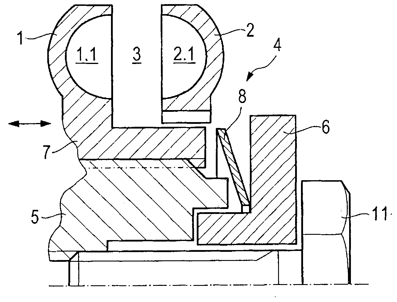
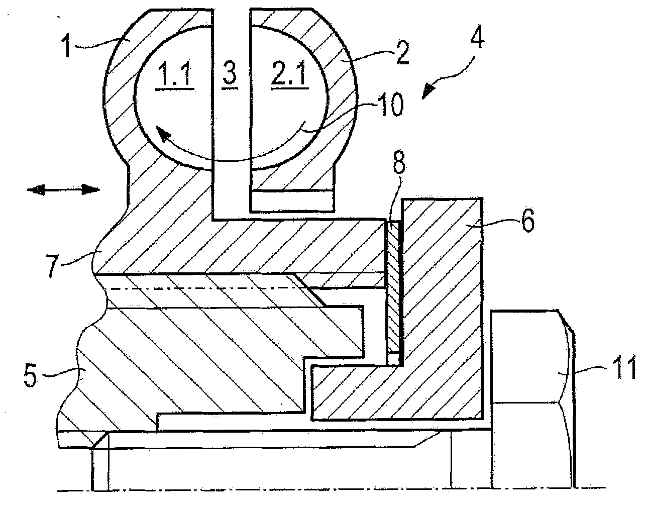
[0031] exist Figure 1a A hydrodynamic brake with a primary impeller 1 and a secondary impeller 2 is shown in . The primary impeller 1 is the rotor of the brake and the secondary impeller 2 is the stator of the brake. Both impellers 1 , 2 have a subarea with blades, ie the rotor has a subarea 1.1 and the stator has a subarea 2.1.

[0032] The stator, ie the secondary impeller 2 , can be supported by a housing (not shown), which encloses the primary impeller 1 together with the stator, for example. The impeller-mounted subregions 1.1, 2.1 of the two front impellers 1, 2 form the torus-shaped working chamber 3.

[0033] The impeller is supported by a subregion 1 . 1 of the primary impeller 1 , which is now displaceable in the axial direction of the hydrodynamic brake, as indicated by the double arrow. This axial displaceability is achieved by the fact that the primary impeller 1 is mounted on the shaft 5 by means of the hub 7 , which currently has internal teeth or an internal...


PUM


Abstract

The hydrodynamic retarder comprises a bladed primary wheel (1) and a bladed secondary wheel (2), which together forms a working chamber (3) filled with working medium. One of the two wheels is axially displaceable with its bladed subareas (1.1,2.1) corresponding to the other wheel. A delay unit (4) is provided for damping the striking of the wheel against a stop (6) during the axial displacement of the wheel into the braking position or non-braking position.

Description

technical field [0001] The invention relates in particular to a hydrodynamic brake according to the preamble of claim 1, having two impellers, a primary impeller and a secondary impeller, at least one of which can be moved relative to the other axial movement. Background technique [0002] The displaceability of at least one of the two impellers serves to reduce the power loss of the hydrodynamic brake when it is unloaded. DE 10219753A1 exemplifies a brake in which the primary impeller (rotor) is mounted on a hollow shaft by means of a screw thread, and during the transition from braking operation to non-braking operation, i.e. in no-load, the primary impeller is kept away from the secondary impeller (stator). In order to return to braking operation, the rotor again approaches the stator, so that a flow circuit can be formed in the working space between the rotor and the stator, by means of which the torque can be transmitted from the rotor to the stator, so that the rotor...

Claims


Application Information

Patent Timeline
Patent Type & Authority Applications(China)
IPC IPC(8): B60T1/087
CPCF16D57/04F16D57/007B60T10/02
Inventor 迪特尔・劳克曼托马斯・奥赫尔亚历山大・施雷贝尔
Owner VOITH PATENT GMBH
Why Eureka
Try Eureka