Eureka AIR delivers breakthrough ideas for toughest innovation challenges, trusted by R&D personnel around the world.

Outer-rotor fluid power machine

An external rotor and power machine technology, applied in the field of power machinery, can solve problems such as loss of energy and inability to meet special needs, and achieve the effect of reducing energy loss

Active Publication Date: 2014-07-30
TONGZHOU XINGCHEN MACHINERY
View PDF6 Cites 0 Cited by
  • Summary
  • Abstract
  • Description
  • Claims
  • Application Information

AI Technical Summary

Problems solved by technology

Various expansion power machines can be suitable for high temperature and high pressure, medium temperature and medium pressure, low temperature and low pressure fluids, and can also be adapted to gas-liquid two-phase fluids, which are also inner rotor structures. In addition, the flow direction of the fluids of various expansion power machines is either axial flow or Flow along the diameter-axial direction, this flow direction is opposite to the direction of the centrifugal force generated by the impeller on the fluid particle, and part of the energy will be lost. Only one side of the scroll expander is a fixed shaft, and the other side is a rotating shaft, and the moving impeller is embedded In the stationary impeller, the fluid vortex flows along the axis-radial direction, but the outflow mode of its existing structure cannot meet some special needs that require outward discharge along the radial direction

Method used


Image

  • Outer-rotor fluid power machine
  • Outer-rotor fluid power machine
  • Outer-rotor fluid power machine

Examples


Embodiment Construction

[0017] The present invention will be further described below in conjunction with the accompanying drawings.

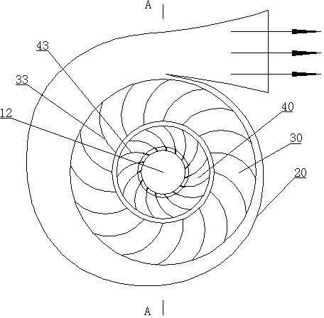
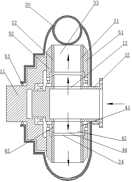
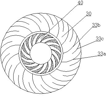
[0018] like figure 1 , figure 2 The shown impeller-type external rotor fluid power machine is mainly composed of a shaft, a casing 20, an impeller 30, and a flow guide 40. Side walls 31, 32, an annular closed impeller with blades 33 installed between the two side walls, the deflector 40 has side walls 41, 42 on both sides, and guide vanes 43 are installed between the two side walls An annular body, the impeller 30 is set on the outer circle of the deflector 40, the shaft is formed by concentrically fitting one end of a moving shaft 11 on one end of a hollow fixed shaft 12, and the deflector 40 is installed on the hollow fixed shaft 12, One end surface of the hollow fixed shaft 12 is closed, and the other end surface is provided with an inlet and communicated with the inlet pipe. The circumference of the hollow fixed shaft 12 in contact with the deflector 40 is provi...


PUM


Abstract

The invention provides an outer-rotor fluid power machine, which belongs to the field of fluid power machinery and mainly aims at enabling fluid to flow in a motor along radial direction and enabling flow direction of the fluid to be basically identical with the direction of centrifugal force the fluid bears so as to decrease energy consumption. The outer-rotor fluid power machine is mainly composed of a shaft, a casing, an impeller, a fluid guiding device and the like. The impeller and the fluid guiding device are sleeved concentrically, the shaft is sleeved concentrically at one end of a hollow fixed shaft through one end of a moving shaft, and the fluid guiding device is installed on the hollow fixed shaft. One end face of the hollow fixed shaft is closed, and the other end face of the hollow fixed shaft is open and communicated with a fluid inlet pipeline. Fluid guiding holes corresponding to fluid channels among fluid guiding blades of the fluid guiding device are arranged on the circumference where the hollow fixed shaft is contacted with the fluid guiding device, the moving shaft is further connected with the side wall of the impeller on one side of the closed end face corresponding to the hollow fixed shaft, and the casing is sleeved outside the fluid guiding device and the impeller. The outer-rotor fluid power machine is simple in structure and easy to process, and can serve as a fluid power machine to be used.

Description

technical field [0001] The invention relates to fluid and thermodynamic machinery, in particular to a power machinery that converts input fluid energy into mechanical energy output. Background technique [0002] Existing fluid motors (fluid power machinery) mainly include: hydraulic motors, pneumatic motors, axial expansion power machines, centripetal expansion power machines, radial-axial flow expansion power machines, vortex expansion power machines, screw expansion power machines, etc., all of which are A device that converts the kinetic energy, pressure energy and heat energy contained in the energy flow into mechanical energy. All kinds of hydraulic motors and air motors are small in size, wide in speed range, and can be adjusted steplessly. Generally, the energy flow is supplied by a special hydraulic station and air pressure station, and the rated pressure is above 10 MP. All of the above are internal rotors. structure. Various expansion power machines can be suitab...

Claims


Application Information

Patent Timeline
Patent Type & Authority Patents(China)
IPC IPC(8): F01D1/06
Inventor 王政玉王超颖张玉芹
Owner TONGZHOU XINGCHEN MACHINERY
Why Eureka
Eureka Blog
Learn More