Eureka AIR delivers breakthrough ideas for toughest innovation challenges, trusted by R&D personnel around the world.

A self-fan-cooled axial flux motor with hybrid integrated centrifugal fan and axial fan

A centrifugal fan and axial flow fan technology, which is applied to electromechanical devices, electrical components, electric components, etc., can solve the problems of large axial installation size of radial flux motors, low power density and efficiency, and inability to dissipate heat away. , to achieve compact structure, improve power density and torque density, and reduce losses

Active Publication Date: 2022-04-05
ANHUI UNIVERSITY
View PDF16 Cites 1 Cited by
  • Summary
  • Abstract
  • Description
  • Claims
  • Application Information

AI Technical Summary

Problems solved by technology

[0002] In the field of emergency power generation, most of the integrated starters / engines are AC permanent magnet synchronous motors, DC motors or AC asynchronous motors with radial flux. Due to the large axial installation size of traditional radial flux motors, the power density and efficiency are relatively low. , the application is limited in the field of emergency power generation where space requirements are strict, portability, and power density requirements are high
[0003] Conventional low-power axial flux motors generally use fins on the base or the end covers on both sides to dissipate heat. Under the conditions of large assembly errors between the stator core and the end covers, large loads or high speeds, the motor generates a large amount of energy. The heat exchange only depends on the fins of the frame or the fins of the end cover, which often cannot dissipate the heat in time, which brings great challenges to the insulation and temperature rise of the motor.

Method used


Image

  • A self-fan-cooled axial flux motor with hybrid integrated centrifugal fan and axial fan
  • A self-fan-cooled axial flux motor with hybrid integrated centrifugal fan and axial fan
  • A self-fan-cooled axial flux motor with hybrid integrated centrifugal fan and axial fan

Examples


Embodiment Construction

[0030] The present invention will be described in detail below in conjunction with the accompanying drawings.

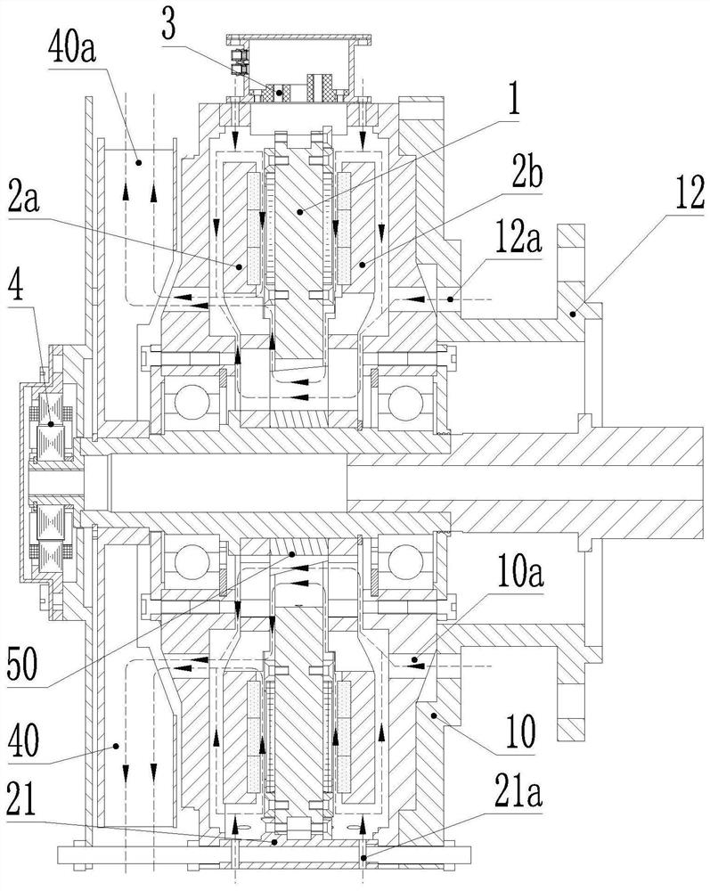
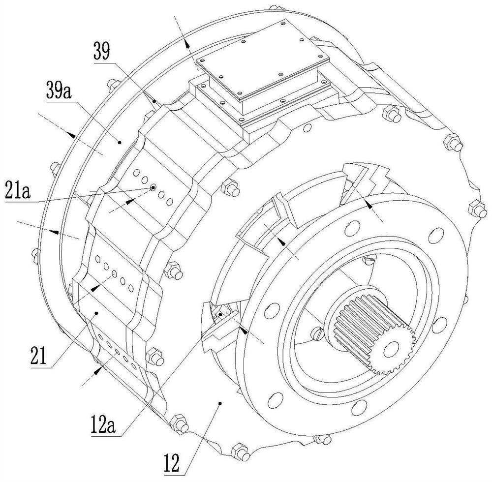
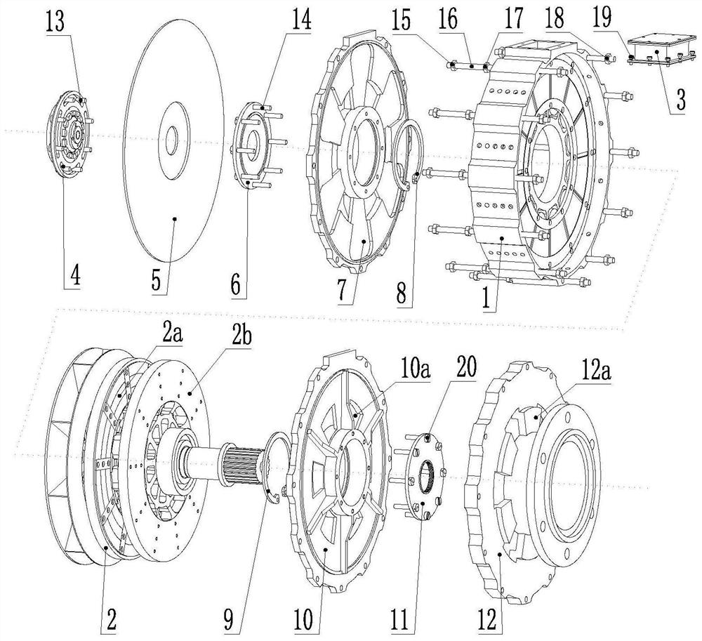
[0031]The magnetic circuit of the self-fan-cooled axial flux motor of the hybrid integrated centrifugal fan and axial flow fan runs through the stator 1 , the driving end rotor 2 b and the non-driving end rotor 2 a. The air path adopts a two-stage fan cooling scheme. Its built-in axial flow fan 50 mainly realizes one of the air path branches, which is to enter the air from the first ventilation hole 10a on the end cover 10 on the driving end side and the second ventilation hole 12a on the flange 12; the other branch , is to suck air from the ventilation hole on the driving end side of the casing 21, flow through the air gap air layer on the two side end surfaces of the driving end rotor 2b, and enter the air inlet of the axial flow fan 50. The branch circuit mainly realized by the external centrifugal fan 40 is to suck air from the vent hole on the non-drive end sid...


PUM


Abstract

The present invention proposes a self-fan-cooled axial flux motor that mixes and integrates a centrifugal fan and an axial fan, adopts a double-rotor / single-stator topology, and a single stator is located between the two rotors. Including stator, drive end rotor, non drive end rotor, terminal box, resolver, drive end cover, non drive end cover and secondary fan cooling system consisting of small axial flow fan and large centrifugal fan. The built-in small axial flow fan is located between the two rotors and is responsible for generating axial wind, and the large centrifugal fan is located outside the non-drive end cover and is responsible for exhausting air. Small axial fans, large centrifugal fans, resolver rotors, and two rotors connected coaxially. The end cover of the driving end, the end cover of the non-driving end and the machine base are connected by screws. The stator of the resolver is fixed to the baffle outside the large centrifugal fan, and the outlet box is fixed to the base by screws. The axial flux motor adopting this two-stage fan heat dissipation scheme improves the heat exchange efficiency of the motor.

Description

technical field [0001] The invention relates to an integrated starter / engine applied in the fields of emergency power generation and new energy vehicles, in particular to a self-fan cooling axial flux motor which mixes and integrates a centrifugal fan and an axial flow fan. Background technique [0002] In the field of emergency power generation, the integrated starters / engines are mostly AC permanent magnet synchronous motors, DC motors or AC asynchronous motors with radial flux. Due to the large axial installation size of traditional radial flux motors, the power density and efficiency are relatively low. , the application is limited in the field of emergency power generation where space requirements are strict, portability, and power density are high. [0003] Conventional low-power axial flux motors generally use the fins on the base or the end covers on both sides to dissipate heat. Under the conditions of large assembly errors between the stator core and the end covers...

Claims


Application Information

Patent Timeline
Patent Type & Authority Patents(China)
IPC IPC(8): H02K9/06H02K3/24H02K16/02H02K11/215
CPCH02K9/06H02K3/24H02K16/02H02K11/215
Inventor 陈起旭王群京李国丽卞晓林刘霄
Owner ANHUI UNIVERSITY
Why Eureka
Eureka Blog
Learn More