Low watt consumption permanent magnet offset external rotor hybrid radial magnetic bearing

A permanent magnet bias and hybrid radial technology, applied in the direction of bearings, shafts and bearings, shafts, etc., can solve the problems of weakening the suction force of permanent magnets on the rotor shaft, increasing bearing power consumption, and long axial length, etc., to achieve power consumption Low, reduce copper consumption, the effect of volume reduction

A permanent magnet bias and hybrid radial technology, applied in the direction of bearings, shafts and bearings, shafts, etc., can solve the problems of weakening the suction force of permanent magnets on the rotor shaft, increasing bearing power consumption, and long axial length, etc., to achieve power consumption Low, reduce copper consumption, the effect of volume reduction

CN1752471AInactive Publication Date: 2006-03-29BEIHANG UNIV

Image

  • Low watt consumption permanent magnet offset external rotor hybrid radial magnetic bearing
  • Low watt consumption permanent magnet offset external rotor hybrid radial magnetic bearing
  • Low watt consumption permanent magnet offset external rotor hybrid radial magnetic bearing

Examples


Embodiment Construction

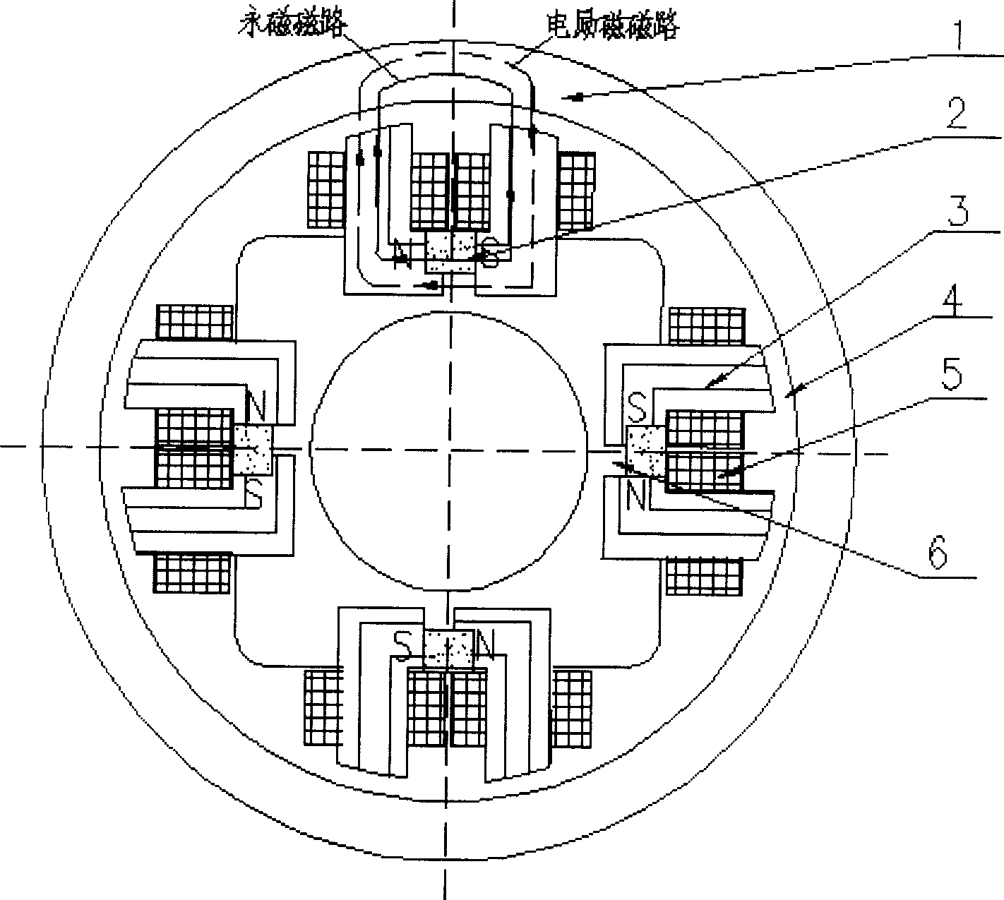
[0010] Such as image 3 As shown, the present invention is composed of a rotor core 1, a permanent magnet 2, a stator core 3, and an excitation coil 5. Eight stator cores 3 magnetic poles form stator core poles in the X and Y directions, and an excitation coil is formed around them. The four permanent magnets 2 are placed between the two stator cores 3 and distributed at 90 degrees. There is a certain gap (generally 0.2-0.4mm) between the outer surface of the stator core 3 and the inner surface of the rotor core 1 to form an air gap 4, and the second air gap between the permanent magnet 2 and the stator core should also be slightly larger than twice the air gap The length of 4 is to reduce the loss of the magnetomotive force of the permanent magnet. The permanent magnet 2 forms a bias magnetic field in the X and Y directions through the stator core 3 poles. In specific applications, the permanent magnet bias outer rotor radial magnetic bearings of the present invention should...


PUM


Abstract

The permanent-magnet offset outer rotor mixed radial magnetic bearing with low power consumption is composed of rotor iron core. Permanent-magnets, stator iron cores and excitation coils. Said invention also provides ther arrangement mode, between outer surface of stator iron core and inner surface of rotor iron core a certain gap is remained to form air gap, between two stator iron cores and permanent magnet a second air gap is formed. The permanent magnet utilizes stator iron core magnet poles to form offset magnetic field on X and Y directions.

Description

Technical field [0001] The invention relates to a non-contact magnetic suspension bearing, in particular to a small-volume, low-power-consumption permanent-magnet-biased outer-rotor radial magnetic bearing, which can be used as a non-contact support for rotating parts in spacecraft such as satellites. Background technique [0002] Magnetic suspension bearings are divided into pure electromagnetic bearings and hybrid magnetic suspension bearings with permanent magnetic bias and electromagnetic control. The former uses large current and consumes a lot of power, and the hybrid magnetic suspension bearings with permanent magnetic bias and electromagnetic control. The magnetic field generated by the permanent magnet bears the main load. Bearing capacity, the electromagnetic field provides auxiliary adjustment bearing capacity, so this kind of bearing can greatly reduce the control current and reduce the loss. However, some of the current permanent magnet bias outer rotor radial m...

Claims


Application Information

Patent Timeline
29 Mar 2006
Publication
CN1752471A
IPC
F16C32/04
CPC
F16C32/0465; F16C2300/20
Inventors
房建成; 孙津济