Automatic calibrating and compensating method of onboard mounting deflection angle of strapdown inertial navigation system

A strapdown inertial navigation and installation deflection technology, which is applied in the field of inertial navigation, can solve the problems of inconsistent heading, aircraft system attitude, heading output error, and installation error angle, etc., to achieve simple engineering use, high precision, and save the need for machinery. The effect of calibration

Active Publication Date: 2012-05-02
FLIGHT AUTOMATIC CONTROL RES INST
View PDF7 Cites 25 Cited by
  • Summary
  • Abstract
  • Description
  • Claims
  • Application Information

AI Technical Summary

Problems solved by technology

[0002] When the strapdown inertial navigation system is installed on the aircraft, the three axes of the mounting bracket coordinate system do not coincide with the three axes of the aircraft body coordinate system, and there is an installation deflection, so the attitude, heading and The actual attitude and heading of the aircraft are inconsistent, which affects the display and control accuracy of the aircraft
In order to meet the requirements of use, the inertial navigation system bracket needs to be calibrated mechanically, and the calibration accuracy is required to be within ±3′, so the coordinate system of the inertial navigation system bracket does not completely coincide with the aircraft body coordinate system, and there is an installation error angle
The inertial navigation system uses the transformation matrix C from the carriage coordinate system to the navigation coordinate system to replace the transformation matrix from the body coordinate system to the navigation coordinate system, and replaces the attitude and heading of the body with the attitude and heading of the carriage extracted from the C matrix, thus causing the aircraft system Attitude, heading output error

Method used


Image

  • Automatic calibrating and compensating method of onboard mounting deflection angle of strapdown inertial navigation system
  • Automatic calibrating and compensating method of onboard mounting deflection angle of strapdown inertial navigation system
  • Automatic calibrating and compensating method of onboard mounting deflection angle of strapdown inertial navigation system

Examples


Embodiment Construction

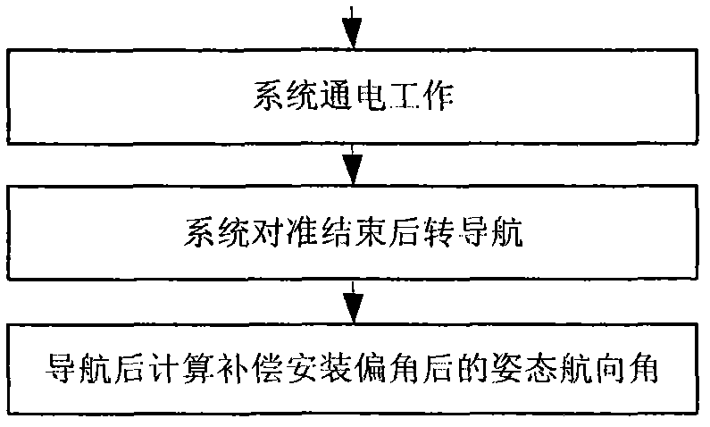
[0051] The declination calibration and compensation of the strapdown inertial navigation system installed on the aircraft are completed in two steps. The specific implementation methods of on-board installation deflection angle calibration and strapdown inertial navigation system installation deflection angle compensation will be described respectively below.

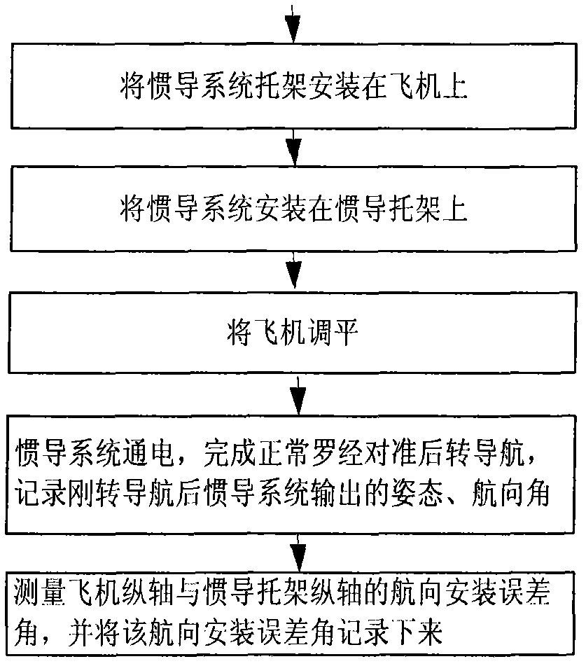
[0052] 1. Implementation method of automatic calibration of deflection angle installed on the strapdown inertial navigation system

[0053] For the automatic calibration flow chart of the on-board declination of the strapdown inertial navigation system, see figure 1 . The calibration of the installation deflection angle of the strapdown inertial navigation system is carried out on the aircraft. After the calibration is completed, the calibrated installation deflection angle is stored. As long as the inertial navigation system mounting bracket is not disassembled again, there is no need to calibrate the mounting defle...


PUM


Abstract

The invention belongs to an inertial navigation technology, particularly relates to an automatic calibrating and compensating method of an onboard mounting deflection angle of a strapdown inertial navigation system. By using the automatic calibrating and compensating method of the onboard mounting deflection angle of the strapdown inertial navigation system, designed by the invention, only one normal compass alignment and navigation is needed after a bracket of the strapdown inertial navigation system is firstly installed on an aircraft, the posture and the heading output by the strapdown inertial navigation system are compared with the reference posture and heading, and the coordinate system of the bracket of the strapdown inertial navigation system and the mounting deflection angle of an aircraft system are automatically calibrated and are stored in a storage unit of the strapdown inertial navigation system. The mounting deflection angle is precisely compensated in the normal working process of the strapdown system through designing a mounting deflection angle compensating algorithm in strapdown inertial navigation system software, and the requirement of the aircraft for the output display and control of the posture, the heading and other navigation parameters of the strapdown inertial navigation system is met.

Description

technical field [0001] The invention belongs to the inertial navigation technology, and relates to an automatic calibration and compensation design method of a strapdown inertial navigation system installed on a plane. Background technique [0002] When the strapdown inertial navigation system is installed on the aircraft, the three axes of the mounting bracket coordinate system do not coincide with the three axes of the aircraft body coordinate system, and there is an installation deflection, so the attitude, heading and The actual attitude and heading of the aircraft are inconsistent, which affects the display and control accuracy of the aircraft. In order to meet the requirements of use, the inertial navigation system bracket needs to be calibrated mechanically, and the calibration accuracy is required to be within ±3′. Therefore, the coordinate system of the inertial navigation system bracket and the aircraft body coordinate system do not completely coincide, and there i...

Claims


Application Information

Patent Timeline
Patent Type & Authority Applications(China)
IPC IPC(8): G01C25/00G01C21/16
Inventor 吉翠萍陈璞袁媛
Owner FLIGHT AUTOMATIC CONTROL RES INST
Why Eureka
Try Eureka