Photoelectric conversion access device

An access device, photoelectric conversion technology, applied in electrical components, data exchange network, data exchange through path configuration, etc., can solve the problems of complex frequency and non-adjustment of equipment

Active Publication Date: 2014-03-19
JINQIANMAO TECH CO LTD
View PDF4 Cites 1 Cited by
  • Summary
  • Abstract
  • Description
  • Claims
  • Application Information

AI Technical Summary

Problems solved by technology

[0003] In order to solve the above-mentioned technical problems of complex equipment and non-adjustable frequency, the technical solution provided by the present invention is to provide a photoelectric conversion access device, including a photoelectric conversion unit, a high-frequency coaxial network unit, a low-frequency coaxial network unit, a high-frequency signal A mixing unit, a low frequency signal mixing unit and a frequency adjustment unit; the photoelectric conversion unit is connected to an optical fiber, the high frequency signal mixing unit is connected to the photoelectric conversion unit through the high frequency coaxial network unit, and the high The frequency signal mixing unit is electrically connected to the coaxial cable; the low-frequency coaxial network unit is connected to the photoelectric conversion unit, and is connected to the low-frequency signal mixing unit through the frequency adjustment unit, and the low-frequency signal mixing unit Connected with a coaxial cable; wherein, the photoelectric conversion unit is used for mutual conversion of photoelectric signals; wherein, the high-frequency coaxial network unit is used for modulating high-frequency digital electrical signals and performing high-frequency analog electrical signals Demodulation; wherein, the low-frequency coaxial network unit is used to modulate the low-frequency digital electrical signal, and demodulate the low-frequency analog electrical signal; wherein the high-frequency signal mixing unit is used to transmit the high-frequency coaxial network unit The signal mixed with the cable TV signal is output to the coaxial cable, or the high frequency signal transmitted from the coaxial cable is received; wherein, the low frequency signal mixing unit is used to mix the signal transmitted by the low frequency coaxial network unit with the cable TV signal Output to the coaxial cable, or receive the low-frequency signal transmitted from the coaxial cable; wherein, the frequency adjustment unit is used to control the input and output frequency range of the low-frequency signal

Method used


Image

  • Photoelectric conversion access device
  • Photoelectric conversion access device
  • Photoelectric conversion access device

Examples


Embodiment Construction

[0018] In order to describe the technical content, structural features, achieved goals and effects of the present invention in detail, the following will be described in detail in conjunction with the embodiments and accompanying drawings.

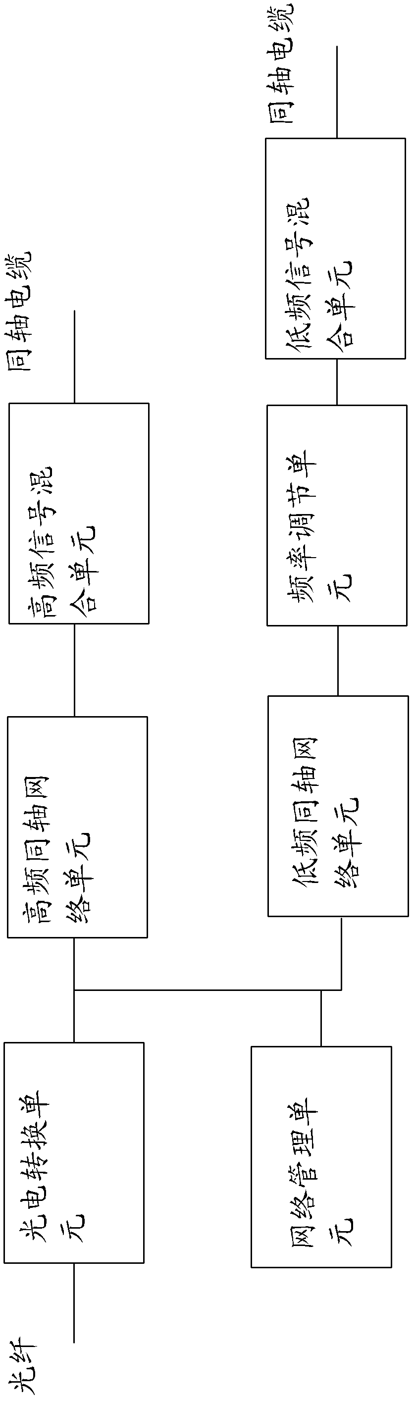
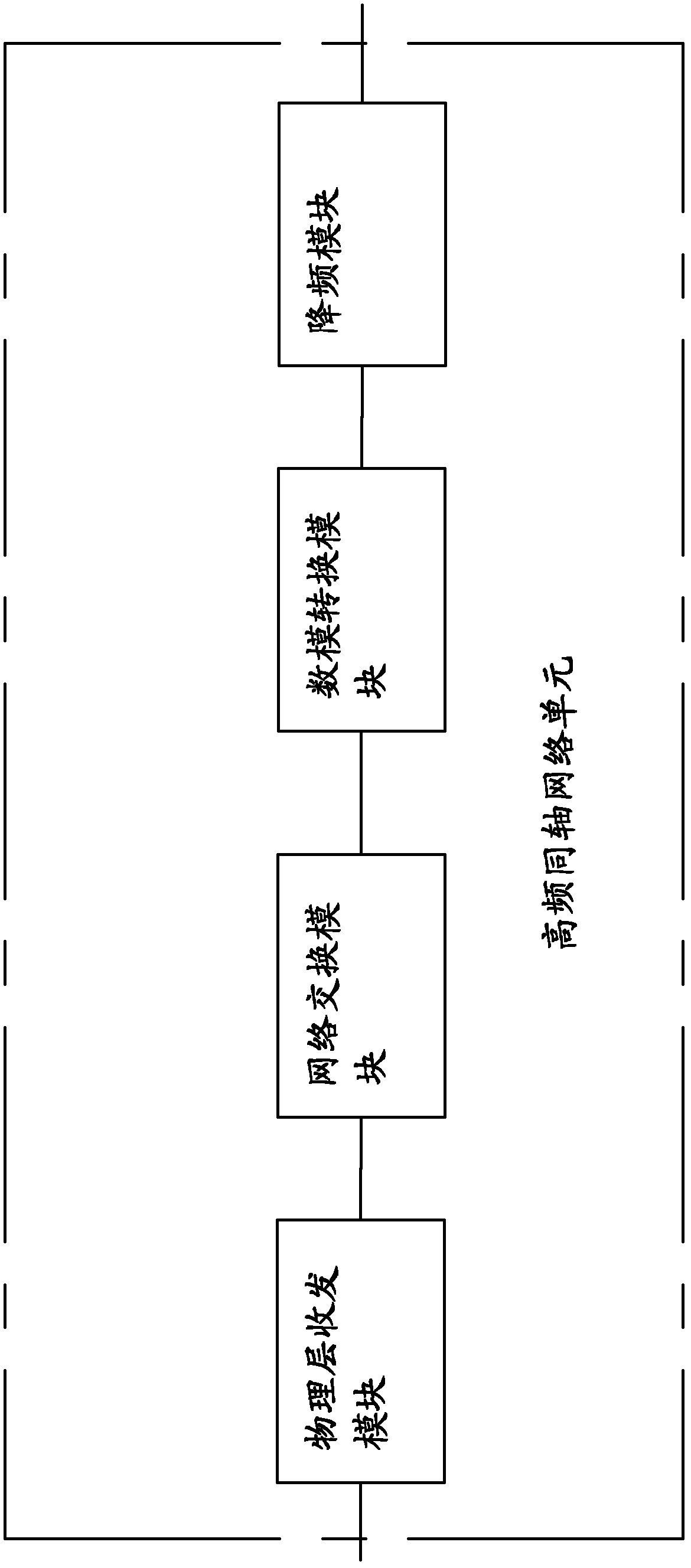
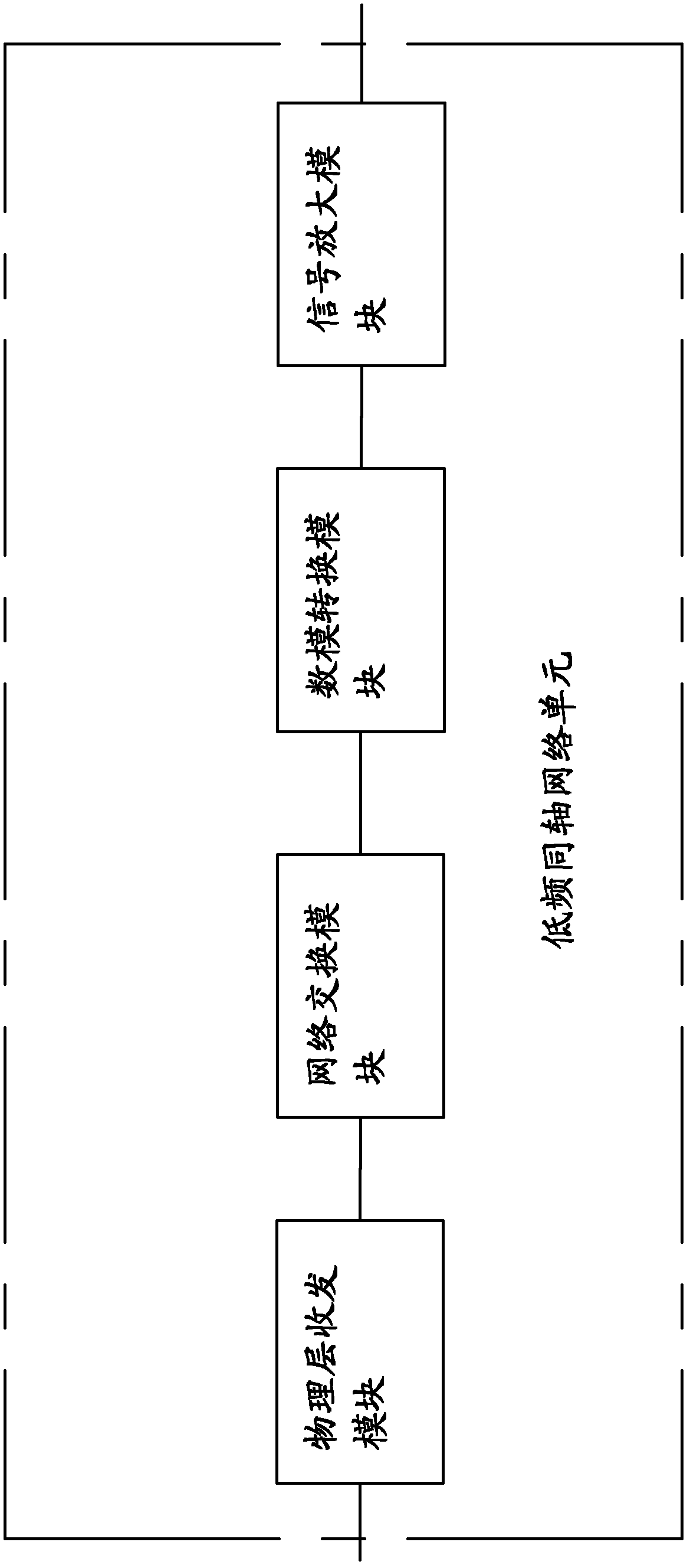
[0019] see figure 1 , the present invention provides a photoelectric conversion access device, which is connected between an optical fiber and a coaxial cable, including a photoelectric conversion unit, a high-frequency coaxial network unit, a low-frequency coaxial network unit, a high-frequency signal mixing unit, and a low-frequency signal mixing unit unit and a frequency adjustment unit; the photoelectric conversion unit is connected to an optical fiber, the high-frequency signal mixing unit is connected to the photoelectric conversion unit through the high-frequency coaxial network unit, and the high-frequency signal mixing unit is connected to the same The low-frequency coaxial network unit is connected to the photoelectric conversion...


PUM


Abstract

The invention provides a photoelectric conversion access device, which is arranged between an optical fiber and a coaxial cable, and comprises a photoelectric conversion unit, a high-frequency coaxial network unit, a low-frequency coaxial network unit, a high-frequency signal mixing unit, a low-frequency signal mixing unit and a frequency adjusting unit; the photoelectric conversion unit is connected with the optical fiber, the high-frequency signal mixing unit is connected with the photoelectric conversion unit through the high-frequency coaxial network unit, and the high-frequency signal mixing unit is electrically connected with the coaxial cable; and the low-frequency coaxial network unit is connected with the photoelectric conversion unit and is connected with the low-frequency signal mixing unit through the frequency adjusting unit, and the low-frequency signal mixing unit is connected with the coaxial cable. The photoelectric conversion access device has a photoelectric conversion function and a frequency adjusting function and is unnecessary to be connected with an external photoelectric conversion device, so the device is simplified.

Description

technical field [0001] The invention relates to a coaxial cable access device, in particular to a photoelectric conversion access device. Background technique [0002] With the development of the integration of the three networks, broadcasting network broadband, video on demand, IP fixed-line and other services are also developing. The existing broadcasting network is mostly composed of coaxial cables, and the network access equipment provided by the existing technology is only connected to the optical fiber. Between the five types of lines, it is not possible to convert the optical fiber signal into an electrical signal that can be transmitted on the coaxial cable. Therefore, it is necessary to add other conversion equipment to realize the communication between the optical fiber and the coaxial cable. It is complicated and costly, and the operating frequency of this equipment cannot be adjusted, so it may overlap and interfere with certain frequency bands of radio and telev...

Claims


Application Information

Patent Timeline
Patent Type & Authority Patents(China)
IPC IPC(8): H04L12/28H04L12/24
Inventor 林涛黄宗荣郑敏忠
Owner JINQIANMAO TECH CO LTD
Why Eureka
Try Eureka