DC combiner box

A technology of DC confluence and confluence busbars, applied in photovoltaic power generation, photovoltaic modules, automatic disconnection emergency protection devices, etc., can solve the problems of inaccurate data, inconvenient installation of combiner boxes, etc., achieve fewer line connection points, reduce product The failure rate and the effect of fewer wires

Pending Publication Date: 2019-09-10
XUCHANG XUJI WIND POWER TECH +1
View PDF1 Cites 1 Cited by
  • Summary
  • Abstract
  • Description
  • Claims
  • Application Information

AI Technical Summary

Problems solved by technology

[0003] The purpose of the present invention is to provide a DC combiner box, which is used to solve the problem of inconv

Method used


Image

  • DC combiner box

Examples


Embodiment 1

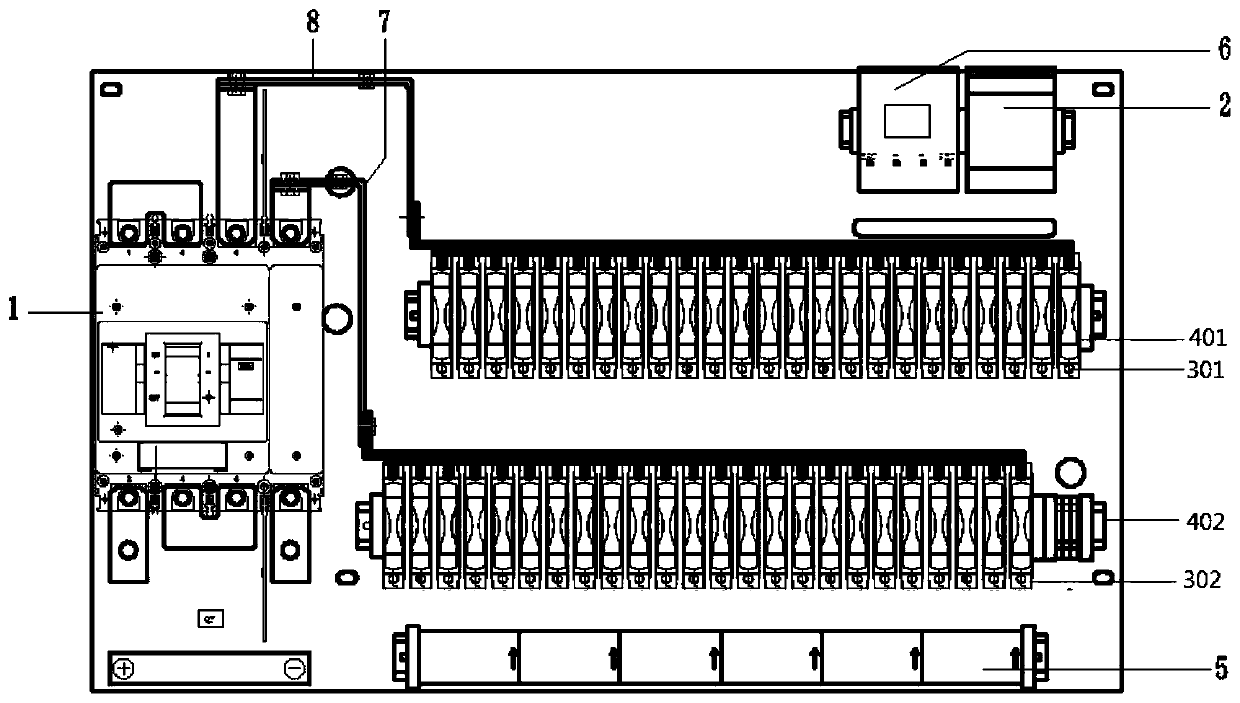
[0022] Such as figure 1 The shown DC combiner box includes a box body in which a positive electrode confluence branch, a negative electrode confluence branch, a monitoring device 6 and a lightning protection device 2 are arranged. Among them, the positive confluence branch is sequentially connected with the positive terminal, the positive fuse 301, the positive confluence busbar 8, the positive terminal of the circuit breaker 1 and the positive terminal; the negative confluence branch is connected with the negative terminal and the current sensor 5 in sequence. , Negative pole fuse 302, negative pole bus bar 7, negative terminal and negative terminal of circuit breaker 1. Among them, the positive input terminal and the negative input terminal are used to connect the positive input cable and the negative input cable respectively, and the positive output terminal and the negative output terminal are used to connect external devices (such as inverters, etc.).

[0023] When actua...

Embodiment 2

[0031] This embodiment proposes a DC combiner box whose composition is the same as that of the DC combiner box in Embodiment 1 of the combiner box. The positive terminal, the current sensor, the positive fuse, the positive busbar, the positive terminal of the circuit breaker, and the positive outgoing terminal are sequentially connected to the confluence branch; the negative terminal, the negative fuse and the negative confluence are connected to the negative confluence branch in sequence Busbar, circuit breaker negative terminal and negative terminal.

[0032] Since the working principle of the DC combiner box in this embodiment is the same as the DC combiner box in the first embodiment of the combiner box, and the introduction of the working principle of the DC combiner box in the first embodiment of the combiner box is complete enough, this embodiment will not repeat.


PUM


Abstract

The invention relates to a DC combiner box, which belongs to the technical field of combiner devices for photovoltaic power generation. The DC combiner box comprises a box body. The box body is internally provided with combiner branches of which each is connected with an incoming end, a current sensor, a fuse, a combiner bus-bar, a circuit breaker and an outgoing end in turn. A monitoring device is arranged in the box body for being in collection connection with the current sensor. The current sensor of the DC combiner box is directly connected to the incoming ends of the combiner branches, sothat the current sensor can detect a current from an external input cable of the DC combiner box directly without going through the fuses, and the measurement is more accurate and reliable. Moreover,because the current sensor is located between the incoming ends and the fuses, a combiner box manufacturer does not need to connect the fuse by a wire, pass the wire through the current sensor and then connect the wire to the combiner bus-bar in order to connect the combiner branches and can directly connect the current sensor, the fuses and the combiner bus-bars in turn, the installation is convenient, and the efficiency of installation is improved.

Description

technical field [0001] The invention belongs to the technical field of junction devices for photovoltaic power generation, and in particular relates to a DC junction box. Background technique [0002] In the prior art, the Chinese utility model patent with the authorized announcement number CN201878049U discloses a smart combiner box for photovoltaic power generation. Current through the fuse. The combiner box manufacturer needs to use a wire to connect the fuse first, then pass through the Hall sensor, and then connect to the busbar to complete the positive (negative) line connection. At the operating site, it is used after the client input cable is directly connected to the fuse. The disadvantages and disadvantages of this product are that the combiner box is inconvenient to install in the factory, requires more connecting wires, complex process, many production hours, low efficiency, many connection points and many parts passing through the line, which is prone to loose...

Claims


Application Information

Patent Timeline
IPC IPC(8): H02S40/34H02H3/087H02J13/00
CPCH02H3/087H02J13/0003H02S40/34Y02E10/50
Inventor 唐涛费怀胜王萌刘德林李延青杨晓光张聪刘二恩陈楠王珂
Owner XUCHANG XUJI WIND POWER TECH
Why Eureka
Try Eureka