Long-distance wireless intelligent monitoring system
What is Al technical title?
Al technical title is built by PatSnap Al team. It summarizes the technical point description of the patent document.
An intelligent monitoring system and remote wireless technology, applied in the direction of closed-circuit television system, etc., can solve problems such as failure to detect danger in time, paralysis of the monitoring system, poor monitoring flexibility, etc., so as to reduce the possibility of human sabotage, simplify operation and control, and improve reliability. sexual effect
Inactive Publication Date: 2012-05-02
大连顺维信息技术有限公司
View PDF0 Cites 7 Cited by
Summary
Abstract
Description
Claims
Application Information
AI Technical Summary
This helps you quickly interpret patents by identifying the three key elements:
Problems solved by technology
Method used
Benefits of technology
Problems solved by technology
However, because the existing monitoring system uses wired transmission, there are problems such as difficult wiring, long construction period and high construction cost. If criminals destroy the wired lines, the entire monitoring system will be paralyzed
In addition, due to the large number of surveillance cameras installed, wired transmission cannot achieve a 1:1 display (that is, each channel of video is equipped with a monitor), and it is impossible to arrange enough monitoring personnel to monitor all videos continuously. Therefore, Only some key videos can be monitored, and a large number of video sources can only be saved by automatic recording, and dangerous situations cannot be detected in time
Wired transmission also limits the installation location of surveillance cameras, and the flexibility of surveillance is poor
Method used
Image
Click on the blue label to locate the original text in one second.
Reading with bidirectional positioning of images and text.
Examples
Embodiment Construction
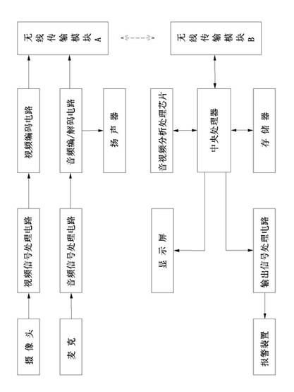
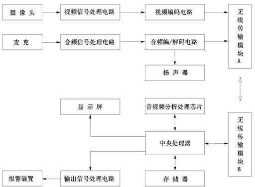
[0007] The specific implementation manner of the present invention will be described below with reference to the accompanying drawings. Such as figure 1 Shown: Same as the prior art, it is provided with a camera and a microphone, a video signal processing circuit (photoelectric coupling, amplification, A / D conversion) is connected with the camera, and an audio signal processing circuit (photoelectric coupling, amplification, etc.) is connected with the microphone , A / D conversion), the difference from the prior art is that the video signal processing circuit is connected to the wireless transmission module A through the video encoding circuit, and the audio signal processing circuit is connected to the wireless transmission module A through the audio encoding / decoding circuit Connected to the audio encoding / decoding circuit with a speaker; corresponding to the wireless transmission module A is provided with a wireless transmission module B, the wireless transmission module B i...
PUM
Abstract
The invention discloses a long-distance wireless intelligent monitoring system which has the advantages of simplicity in installation, low cost, high reliability and convenience in use. The long-distance wireless intelligent monitoring system is provided with a camera and a microphone, wherein the camera is connected with a video signal processing circuit and the microphone is connected with a voice frequency signal processing circuit; the video signal processing circuit is connected with a wireless transmission module A through a video encoding circuit; the voice frequency signal processing circuit is connected with the wireless transmission module A through a voice frequency encoding/decoding circuit, and a loudspeaker is connected with the voice frequency encoding/decoding circuit; a wireless transmission module B is arranged correspondingly to the wireless transmission module A; the wireless transmission module B is connected with a central processing unit; a memorizer and a voice frequency/video analysis processing chip are connected with the central processing unit; and the output end of the central processing unit is connected with a display screen and the output end of the central processing unit is connected with an alarming device through an output signal processing circuit.
Description
technical field [0001] The invention relates to a safety monitoring device, in particular to a remote wireless intelligent monitoring system with simple installation, low cost, high reliability and convenient use. Background technique [0002] At present, many public places (such as forests, highways, factories, airports, ports, oil fields, schools, squares, hospitals, parks, residential quarters, etc.) have installed a large number of surveillance cameras (including microphones), and the collected audio and video The signal is transmitted to the monitoring center. However, because the existing monitoring system uses wired transmission, there are problems such as difficult wiring, long construction period and high construction cost. If criminals destroy the wired lines, the entire monitoring system will be paralyzed. In addition, due to the large number of surveillance cameras installed, wired transmission cannot achieve a 1:1 display (that is, each channel of video is equi...
Claims
Application Information
Patent Timeline
Application Date:The date an application was filed.
Publication Date:The date a patent or application was officially published.
First Publication Date:The earliest publication date of a patent with the same application number.
Issue Date:Publication date of the patent grant document.
PCT Entry Date:The Entry date of PCT National Phase.
Estimated Expiry Date:The statutory expiry date of a patent right according to the Patent Law, and it is the longest term of protection that the patent right can achieve without the termination of the patent right due to other reasons(Term extension factor has been taken into account ).
Invalid Date:Actual expiry date is based on effective date or publication date of legal transaction data of invalid patent.