
Offshore multi-directional self-elevating petroleum drilling platform

A self-elevating platform, multi-directional technology, applied in the field of machinery, can solve problems such as inability to drill in multiple directions, platform overturning, foundation damage, etc., to achieve high promotion and application value, reduce operation preparation costs, and ensure the effect of safety.

Active Publication Date: 2013-09-25
CHINA UNIV OF PETROLEUM (EAST CHINA) +2
View PDF8 Cites 0 Cited by
  • Summary
  • Abstract
  • Description
  • Claims
  • Application Information

AI Technical Summary

Problems solved by technology

However, if the self-elevating platform is raised and lowered, ballasted, and turned multiple times in the same sea area, the foundation will be severely damaged, and the stability of the platform cannot be guaranteed, resulting in the danger of the platform capsizing, which seriously threatens the platform itself and staff safety
[0003] The present invention is designed to meet the above requirements, and its purpose is to use a turntable reversing mechanism and multi-directional mobile support rails to move the original drilling module on the platform to the steering turntable for reversing and to coordinate with other azimuth rails. Docking, to solve the working problem that conventional platforms can only drill in one direction and cannot drill in multiple directions, and effectively solve the purpose of completing multi-directional and multi-well group drilling operations in designated areas

Method used


Image

  • Offshore multi-directional self-elevating petroleum drilling platform
  • Offshore multi-directional self-elevating petroleum drilling platform
  • Offshore multi-directional self-elevating petroleum drilling platform

Examples


Embodiment Construction

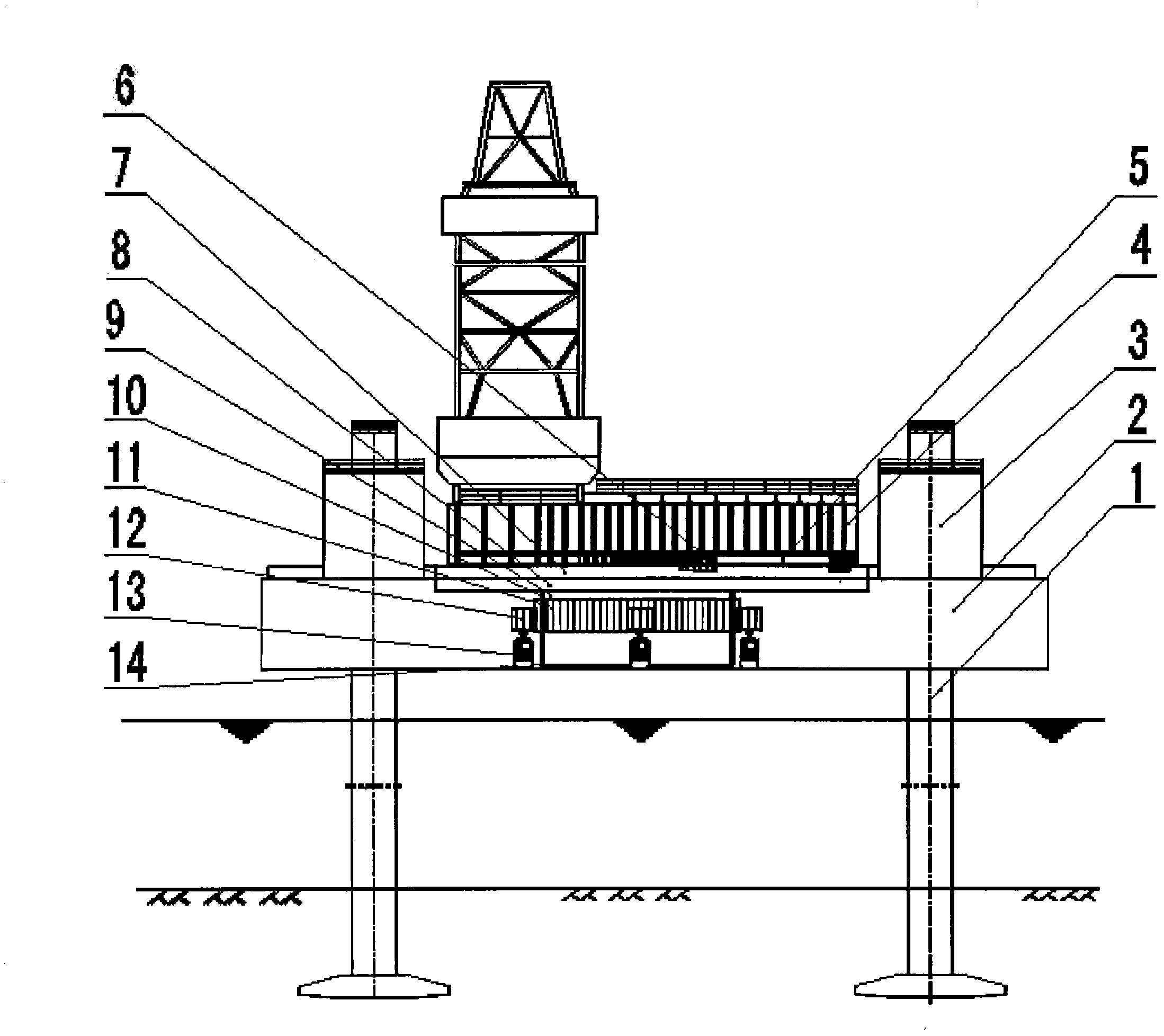
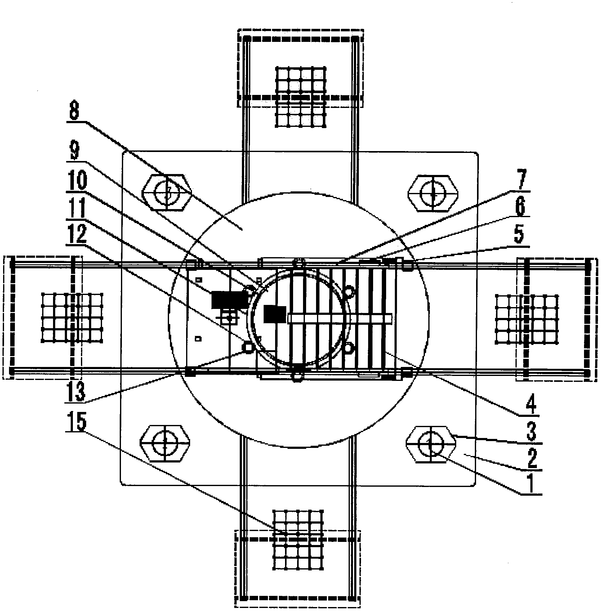
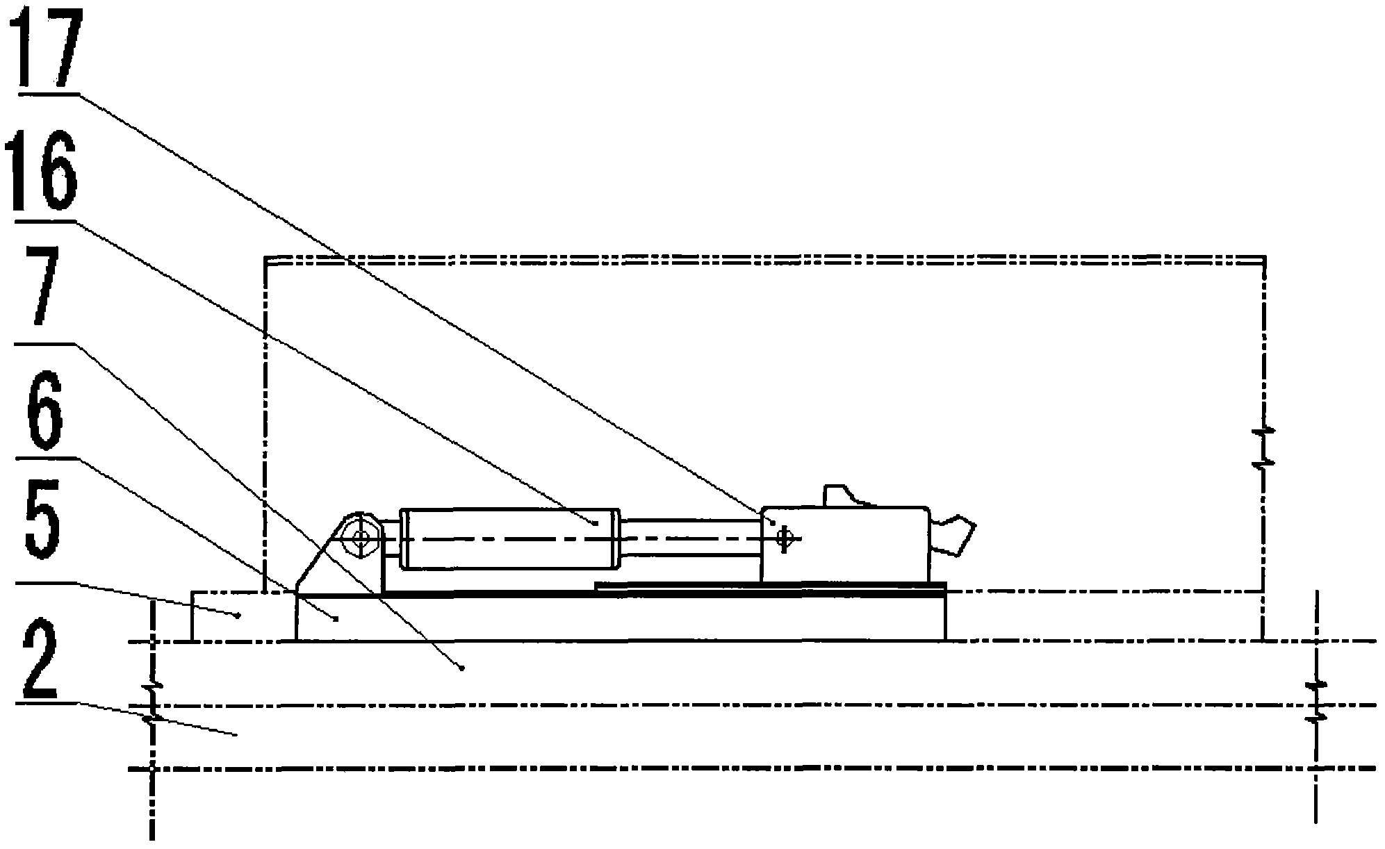
[0017] Now combined with the manual figure 1 , 2,3,4 further describe the present invention: mobile base 5, mobile device 6, mobile support track 7, reversing turntable 8, main shaft 9, rotating shaft 10, drive motor 13 constitute.

[0018] The main body 2 of the jack-up platform lowers the legs 1 to the seabed by means of the lifting device 3. After the platform is in place at sea, the drilling module 4 can move to the required position on the mobile support rail 7 through the moving device 6 and extend the jack-up platform. The cluster well group 15 is drilled outside the main body 2 of the platform. When the well position in one direction is completed, the drilling module 4 is reversely pushed by the mobile device 6 to the reversing turntable 8 and fixed, and the driving motor 13 drives the driving gear 12. Drive the ring gear 11 welded on the rotating shaft 10 to turn the reversing turntable 8 to another working position. During the rotation process, the annular centering ...


PUM


Abstract

The invention discloses an offshore multi-directional self-elevating petroleum drilling platform, which belongs to the field of machinery and comprises movable supporting rails, a reversing turntable, a spindle, a rotary shaft, driving motors and a moving device. The spindle is fixed in the middle of the self-elevating platform body, the rotary shaft is mounted outside the spindle, gear rings are mounted on the periphery of the upper portion of the rotary shaft, driving gears which are distributed uniformly mesh with the gear rings and are connected with the driving motor through couplers, the reversing turntable is fixedly mounted at the upper end of the rotary shaft and is kept on the same horizontal plane with an upper deck of the self-elevating platform body, the movable supporting rail is mounted on the reversing turntable, another movable supporting rail is mounted on the upper deck of the self-elevating platform body corresponding to the position on the reversing turntable where the movable supporting rail is mounted, a movable base is mounted on the movable supporting rails, and a drilling module is mounted on the movable base. The offshore multi-directional self-elevating petroleum drilling platform is capable of drilling in multiple directions within a required range on the periphery of the platform, and operating preparation cost can be reduced greatly.

Description

technical field [0001] The invention relates to a self-elevating platform for offshore multi-directional drilling, which belongs to the field of machinery. Background technique [0002] Jack-up drilling platforms occupy a very important position in the exploration and development of offshore oil and gas fields. The platform is equipped with a drilling module. After being in place at sea, rely on the cantilever beam to extend out from the main body of the platform along the track to drill a cluster well group. For conventional jack-up drilling platforms, the cantilever beam can only move in one direction, so the platform can only perform drilling operations in this direction. With the development of new drilling technologies and new models of offshore development and based on economic considerations, if a high-yield oil area is found in a certain area, it is necessary to drill cluster wells in as small a range as possible in this area to increase productivity. Utilizing the...

Claims


Application Information

Patent Timeline
Patent Type & Authority Patents(China)
IPC IPC(8): E02B17/00
Inventor 曹宇光史永晋张士华孙晓瑜
Owner CHINA UNIV OF PETROLEUM (EAST CHINA)
Learn More