Light guide plate manufacturing method

A manufacturing method and technology for light guide plates, applied in the directions of light guides, optics, optical components, etc., can solve the problems of color deviation, easy residual transfer rate, poor brightness performance of the light guide plate, etc., to improve the color deviation and reduce the number of bubbles. Effect

Inactive Publication Date: 2012-05-16
WIN OPTICAL
View PDF7 Cites 4 Cited by
  • Summary
  • Abstract
  • Description
  • Claims
  • Application Information

AI Technical Summary

Problems solved by technology

[0007] The main purpose of the present invention is to solve the problem of poor brightness and color deviation of the light guide plate due to the low transfer rate and easy residual bubbles and deformation in the known manufacturing method of the light guide plate.

Method used


Image

  • Light guide plate manufacturing method
  • Light guide plate manufacturing method
  • Light guide plate manufacturing method

Examples


Embodiment Construction

[0053] The detailed description and technical content of the manufacturing method of the light guide plate of the present invention are described as follows with the accompanying drawings:

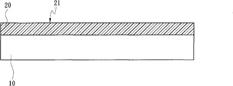
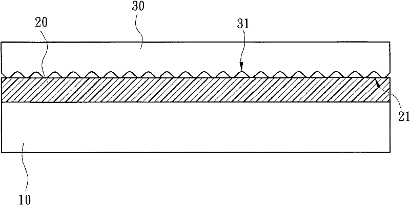
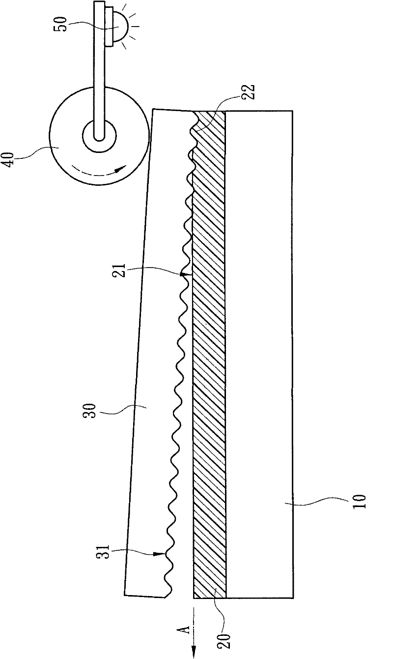
[0054] First, see Figure 1-1 to Figure 1-5 , Is a schematic diagram of the manufacturing process of the first embodiment of the light guide plate manufacturing method of the present invention. First, a substrate 10 is provided, and a resin layer 20 is formed on the substrate 10. The resin layer 20 is preset with a surface 21 to be processed. In this embodiment, the substrate 10 preferably uses a plate, and the resin layer 20 is coated on the substrate 10 in a colloidal state. Then, a rolling device is used to roll the surface 21 to be processed. The rolling device includes an imprinter 30 and at least one pressure roller 40 that abuts against the imprinter 30.

[0055] Such as Figure 1-2 As shown, the imprinter 30 is first placed on the surface 21 to be processed, and the surface of the imprin...


PUM

PropertyMeasurementUnit
thicknessaaaaaaaaaa
refractive indexaaaaaaaaaa
Vickers hardnessaaaaaaaaaa

Abstract

The light guide plate manufacturing method comprises the following steps of: using a rolling depression device comprising an imprinter, wherein the surface of the imprinter comprises a first structure; rolling a resin layer arranged on a substrate by the imprinter, or forming the resin layer on the imprinter to roll the substrate, enabling the resin layer to continuously form a second structure complementary to the first structure, and attaching the second structure on the substrate. The rolling depression area formed by the rolling depression mode is smaller, so the uniformity of pressure application is easy to control, the light guide plate can have high transcription rate, and defects are reduced.

Description

Technical field [0001] The invention relates to a method for manufacturing a light guide plate, in particular to a method for manufacturing a light guide plate with high transfer rate and reduced defect generation. Background technique [0002] As far as the liquid crystal display is concerned, the brightness performance of the backlight module is the key to the overall display performance. Generally speaking, the backlight module is composed of a brightness enhancement film, a diffuser, a light guide plate, a backlight, a reflective sheet and other components. According to the different setting methods, it can be divided into lateral type and direct type. The backlight source of the former is placed on the side of the light guide plate; while the backlight source of the latter is placed between the light guide plate and the reflective sheet. The light emitted from the backlight will enter the light guide plate, and most of the light will be emitted from the three-dimensional dot...

Claims


Application Information

Patent Timeline
Patent Type & Authority Applications(China)
IPC IPC(8): G02B6/00
Inventor 许书豪石清堉
Owner WIN OPTICAL
Why Eureka
Try Eureka