Revision connector for spinal constructs

A technique of vertebral attachment, applied in the field of orthopedics, which can solve the problems of time-consuming, interfering vertebral level, etc.

Active Publication Date: 2012-05-16
SYNTHES GMBH
View PDF12 Cites 25 Cited by
  • Summary
  • Abstract
  • Description
  • Claims
  • Application Information

AI Technical Summary

Problems solved by technology

However, the problem is that this technique may interfere with some previously asymptomatic levels of the spine and thus cause pain that was not previously present.
Options for adding and replacing hardware are time-consuming, especially if the surgeon is unfamiliar with the patient's existing hardware

Method used


Image

  • Revision connector for spinal constructs
  • Revision connector for spinal constructs
  • Revision connector for spinal constructs

Examples


Embodiment Construction

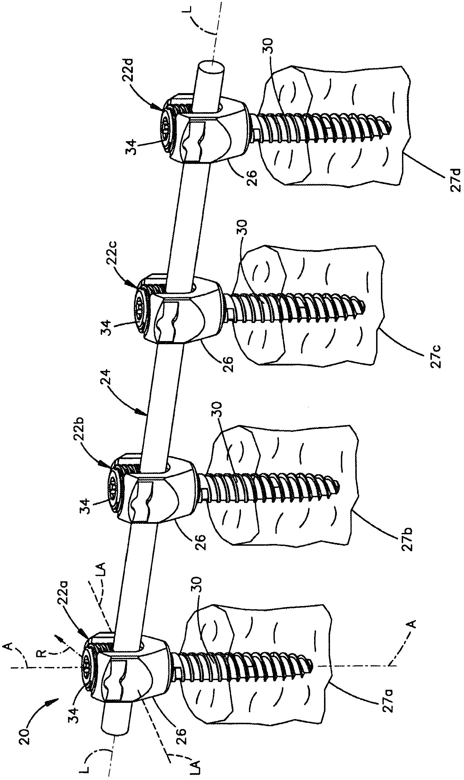
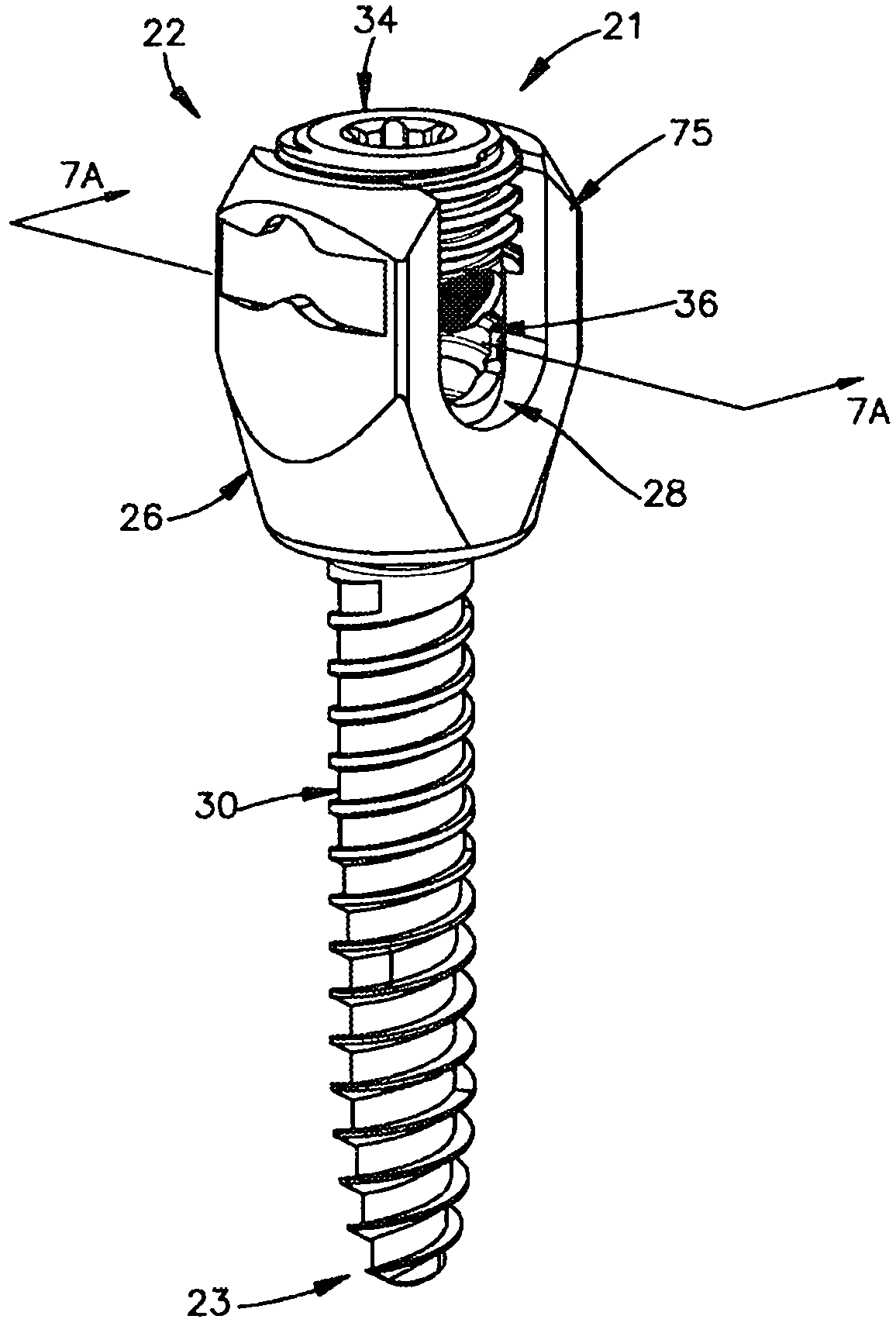
[0035] The specific terminology used in the following description is for convenience only and should not be considered as limiting. For example, bone fixation assembly 20 includes one or more bone fixation elements 22, and Figure 1A Shown in is four bone fixation elements 22A-D. Such as Figure 1B As shown in , each bone fixation element 22 extends vertically along the axial direction A and along a radial direction R extending perpendicularly to the axial direction A. Thus, the radial direction R comprises a longitudinal direction L as well as a transverse direction LA extending perpendicularly to this longitudinal direction L. It should be appreciated that the directional terms "longitudinal" and "transverse" may likewise be used for a horizontally extending bone fixation assembly 20, while the directional term "transverse" may refer to a vertical direction. Bone fixation element 22 defines an upper end 21 and a lower end 23 such that the directional terms "upward" and "do...


PUM


Abstract

An extender system is configured to couple a vertebral bone anchor that has been previously implanted in a vertebra, or is newly implantable in a vertebra, to an adjacent bone, which can be an additional spinal level or an occiput, for example. The extender system includes an extension member having a body and an engagement member coupled to the body. The extension member defines an aperture extending through the engagement member. A screw is configured to attach the extension member to the vertebral bone anchor. The extension member can be fastened to the adjacent bone.

Description

[0001] Cross References to Related Applications [0002] This application claims the benefit of U.S. Provisional Patent Application No. 61 / 187902, filed June 17, 2009, the contents of which are incorporated herein by reference as if in their entirety explained in this article. technical field [0003] The present invention relates generally to orthopedics, and more particularly to implants and methods for extending an existing posterior vertebral screw assembly to an additional stage. Background technique [0004] Existing options for modifying and / or extending posterior vertebral screw and rod structures in a patient are limited. Patients who have had previous spinal surgery often develop adjacent vertebral level disorders, which often cause pain and require additional surgery. Such additional spinal surgery typically entails extending existing hardware structures by one or more additional vertebral levels. In this case, the surgeon must decide whether he can 1) extend t...

Claims


Application Information

Patent Timeline
Patent Type & Authority Applications(China)
IPC IPC(8): A61B17/70
CPCA61B17/7007A61B17/7049A61B17/7001A61B17/7011A61B17/7002A61B17/1671A61B17/7068A61B17/7025A61B17/7032
Inventor A·蒙特洛O·莱文W·斯特劳斯博T·库恩齐
Owner SYNTHES GMBH
Why Eureka
Try Eureka