Installation structure for clip and attachment member

A technology for assembling structures and installing components, which is applied in the direction of connecting components, threaded fasteners, thin plate connections, etc., can solve the problems of difficult alignment of legs and corresponding mounting holes, deterioration of assembly efficiency, etc., and achieve the effect of improving clip insertion operations

Inactive Publication Date: 2014-05-28
PIOLAX CO LTD
View PDF7 Cites 0 Cited by
  • Summary
  • Abstract
  • Description
  • Claims
  • Application Information

AI Technical Summary

Problems solved by technology

[0003] However, when the position of the clip changes within the range defined by this play, alignment of the legs with the corresponding mounting holes becomes difficult during insertion of the legs into the mounting holes, thereby deteriorating assembly efficiency.

Method used


Image

  • Installation structure for clip and attachment member
  • Installation structure for clip and attachment member
  • Installation structure for clip and attachment member

Examples


Embodiment Construction

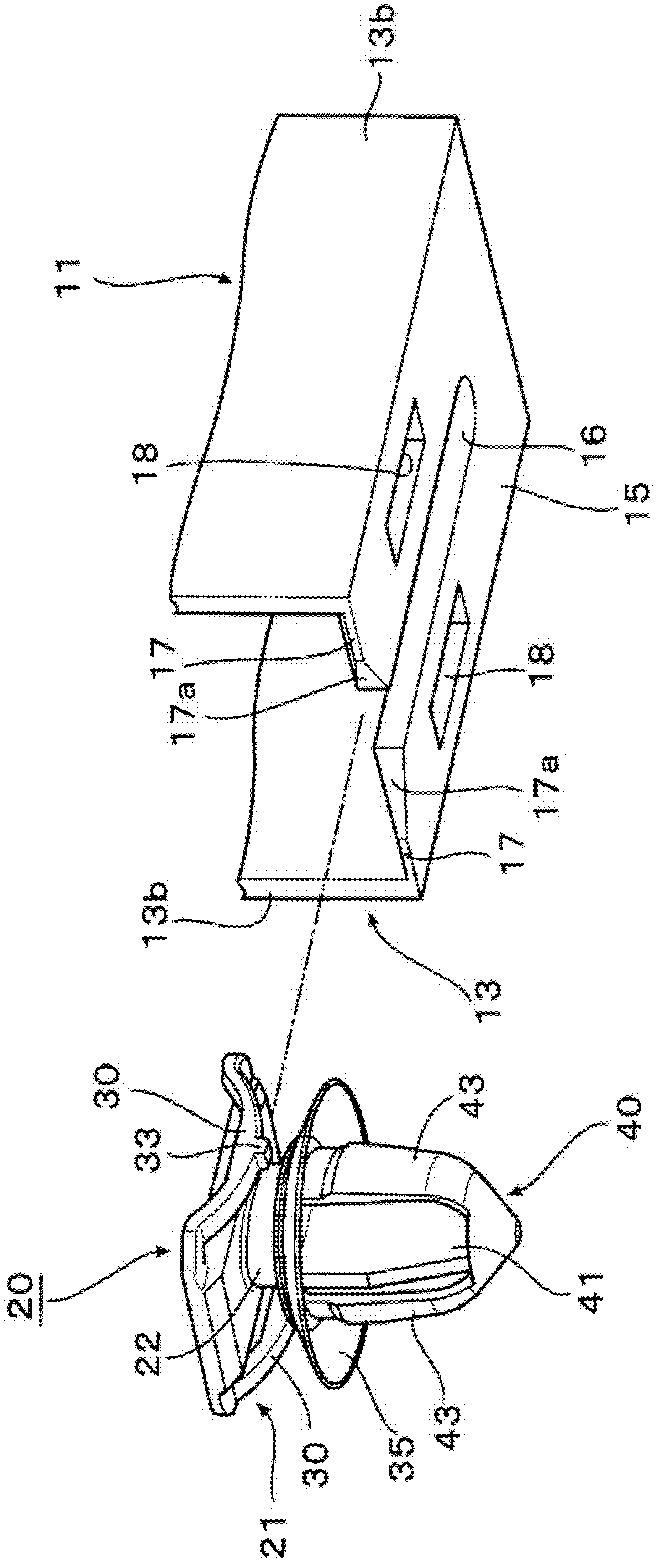
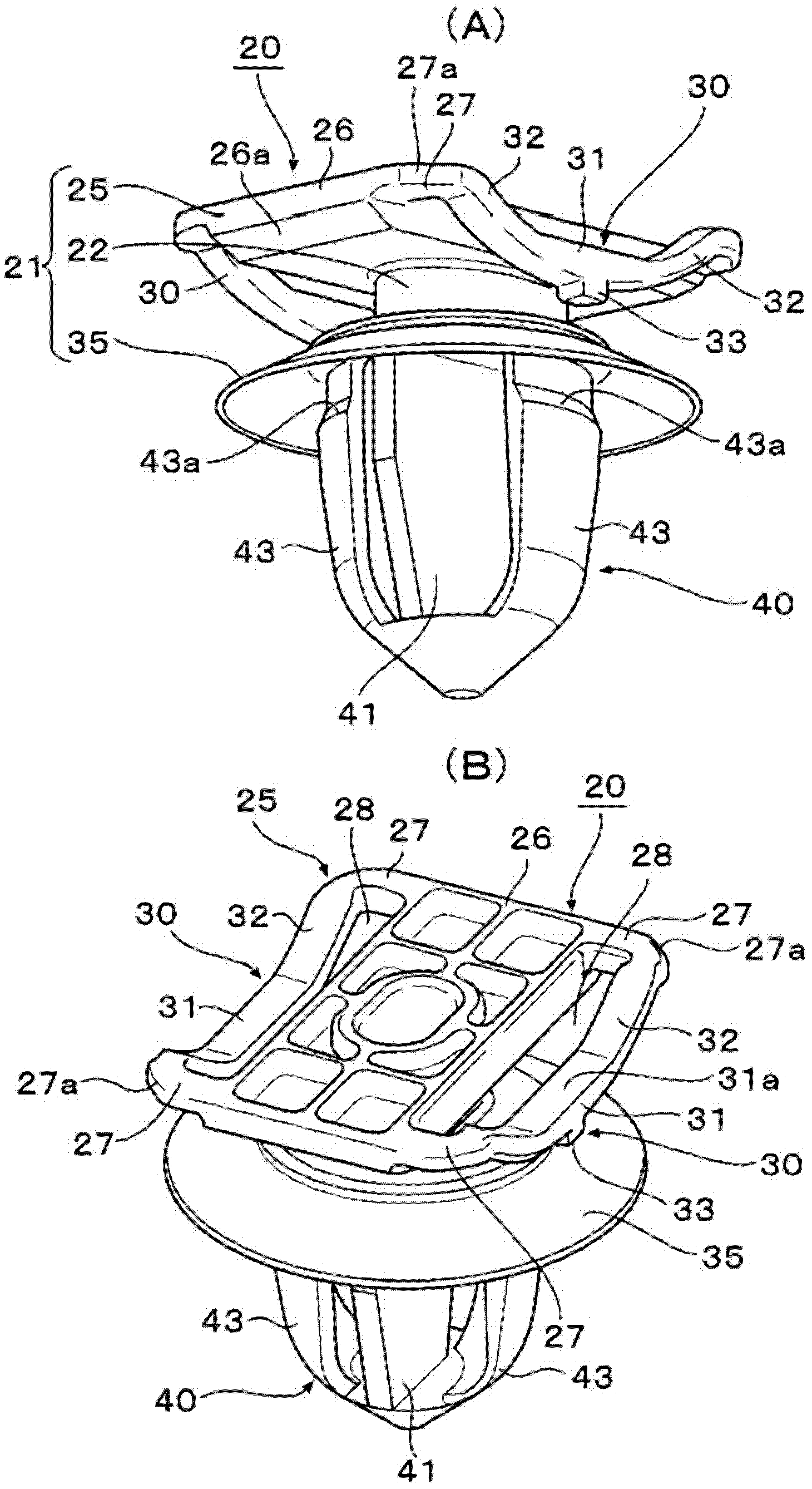
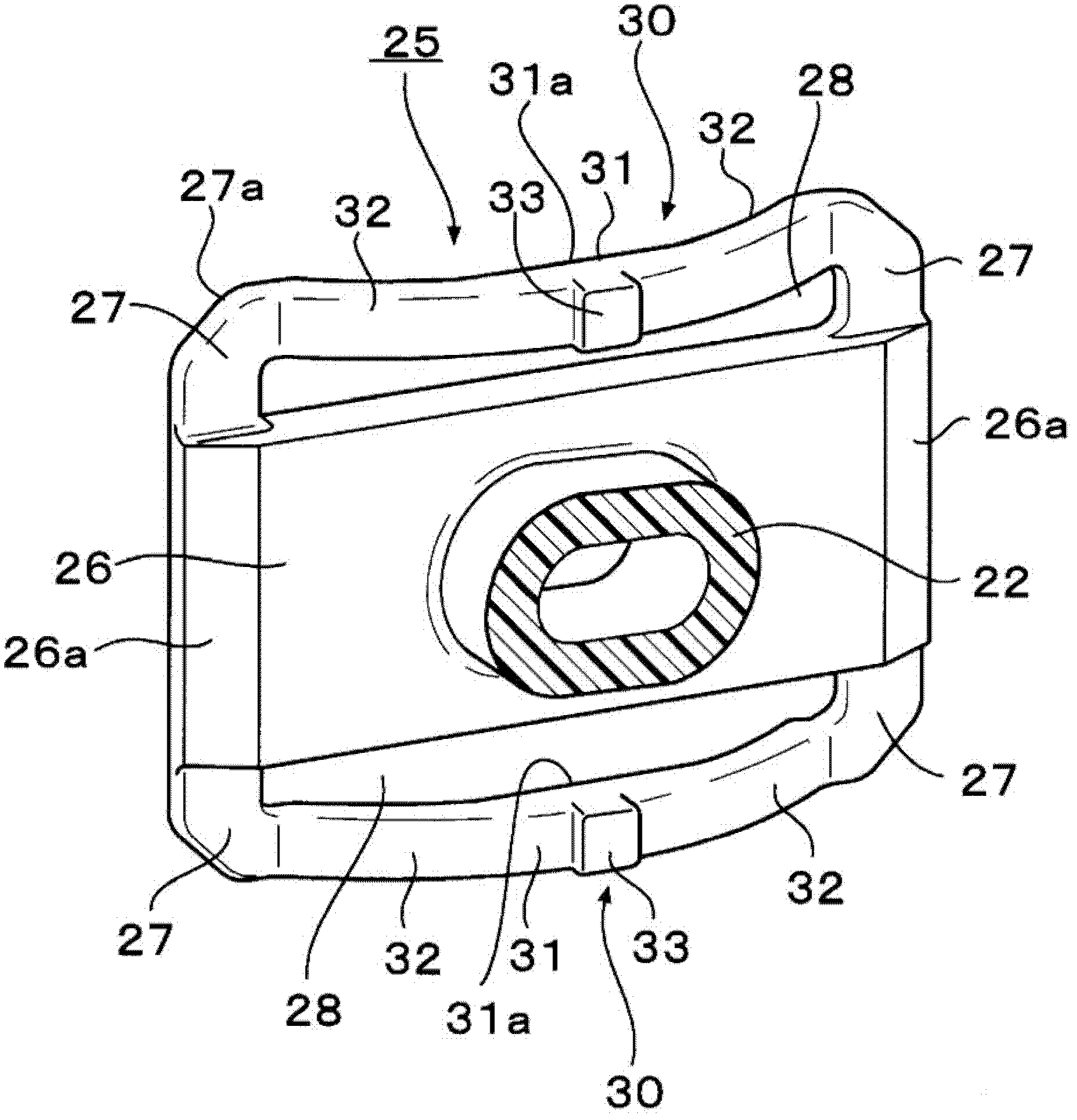
[0035] Such as Figure 8 As shown, for example, a clip 20 is used to mount a mountable part 10 such as an ornament or a trim panel to a supporting part 1 such as a motor vehicle body panel, and the clip 20 has a head 21 and a leg 40 . The head 21 is inserted into the plate-shaped mounting seat 15 formed on the mountable part 10 to be assembled, and the leg part 40 is inserted into the mounting hole 5 formed in the supporting part 1 to be engaged therewith, thereby, via The clip 20 mounts the mountable part 10 on the supporting part 1 .

[0036] In the following, refer to Figure 1 to Figure 8 , describing an embodiment of the assembly structure of the clip and the mountable part according to the present invention.

[0037] First, see figure 1 ,as well as Figure 4 to Figure 8 , describing the structure of the installable part 10. In the present embodiment, a plurality of base frames 11 each having a plate-shaped mounting seat 15 are provided on the rear side of the mounta...


PUM


Abstract

An assembling construction assembles a mountable member to a support member by holding a head portion of a clip on a mounting seat of the mountable member while securely fitting a leg portion in a mounting hole in the support member, the mounting seat has an instruction groove and guide grooves, the head portion of the clip has a first flange portion beam-like strip-shaped elastic pieces and which are brought into press contact with end portions of the guide grooves and stopper projections which are adapted to be brought into engagement with the end portions of the guide grooves when the clip is attempted to be shifted largely relative to the mounting seat.

Description

technical field [0001] The present invention relates to an assembly structure for assembling a clip to an installable part, the clip fixing the installable part and a supporting part. Background technique [0002] For example, clips having a head and legs are used in securing a mountable component such as a trim panel to a supporting component such as an automotive body panel. For example, the mountable part has a mount that fits with the head of the clip. The head of the clip is assembled to the mount, and the leg is inserted into the mounting hole of the support member, whereby the mountable part is fixed to the support member via the clip. At the same time, there will be unavoidable manufacturing dimensional errors between the mountable part and the supporting part. When the mountable member is a longitudinally elongated component such as a lateral air flow stabilizing plate, the dimensional change due to thermal expansion is relatively large. Accordingly, fitting the ...

Claims


Application Information

Patent Timeline
Patent Type & Authority Patents(China)
IPC IPC(8): F16B19/00F16B5/06F16B5/10
CPCF16B5/0657F16B5/065F16B21/086
Inventor 林慎一郎
Owner PIOLAX CO LTD
Why Eureka
Try Eureka