
Heat dissipation structure

A heat dissipation structure and pipe body technology, which is applied in the direction of instruments, electrical digital data processing, digital data processing components, etc., can solve the problem that the heat dissipation structure cannot meet the heat dissipation requirements of a streamlined computer

Inactive Publication Date: 2012-05-23
INVENTEC CORP
View PDF0 Cites 6 Cited by
  • Summary
  • Abstract
  • Description
  • Claims
  • Application Information

AI Technical Summary

Problems solved by technology

[0004] In view of the above problems, the technical problem to be solved by the present invention is to provide a heat dissipation structure

Method used


Image

  • Heat dissipation structure
  • Heat dissipation structure
  • Heat dissipation structure

Examples


Embodiment Construction

[0034] Below in conjunction with accompanying drawing, structural principle and working principle of the present invention are specifically described:

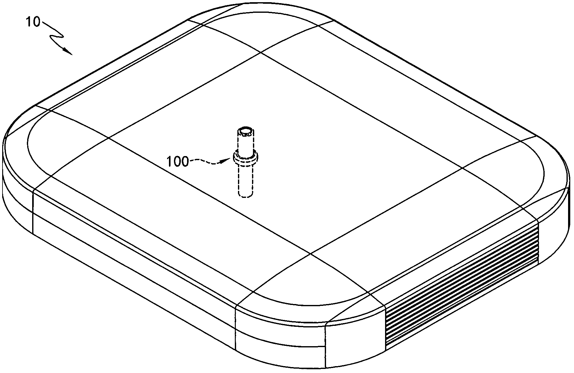
[0035] Please refer to figure 1 , figure 1 Shown is a schematic diagram of a heat dissipation structure applied to a compact computer according to an embodiment of the present invention. The heat dissipation structure 100 of an embodiment of the present invention is used for heat dissipation of an electronic device. For the convenience of description, the electronic device of this embodiment takes the thin computer 10 as an example, but it is not limited thereto.

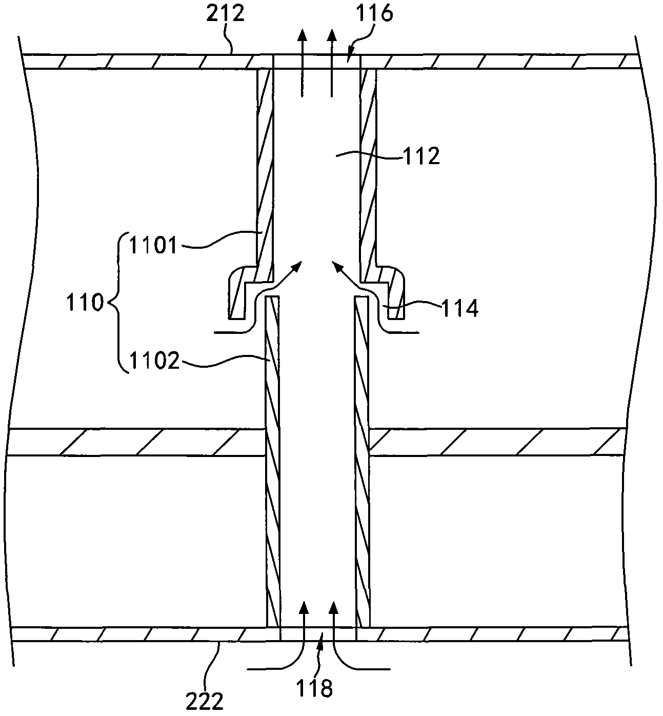
[0036] Please also refer to figure 2 and image 3 , figure 2 Shown is a structural cross-sectional view of a heat dissipation structure according to an embodiment of the present invention, image 3 shown based on figure 2 The enlarged view of the local structure of the heat dissipation structure.

[0037] The compact computer 10 according to an embodiment...


PUM


Abstract

The invention relates to a heat dissipation structure, which is arranged on an electronic device. The heat dissipation structure is provided with a diversion pipe, wherein an airflow channel is arranged in the diversion pipe, and the airflow channel penetrates through a top surface to a bottom surface of the electronic device; the airflow channel is provided with an outlet and an inlet respectively on the top surface and the bottom surface; and the diversion pipe is provided with at least one through hole, the through hole is communicated with the airflow channel and inside of the electronic device, so that hot air inside the electronic device passes through the airflow channel and flows out from the outlet, and external cold air flows into the airflow channel from the inlet to form a circulating airflow.

Description

technical field [0001] The invention relates to a heat dissipation structure, in particular to a heat dissipation structure for electronic equipment without a built-in fan. Background technique [0002] The difference between a thin computer (thin client) and a common personal computer on the market is that the thin client does not have built-in application programs, and redundant functions are omitted. Thin PC can also be said to be a general term for terminals that can be operated by reading data or executing applications after connecting to a server in a network environment. The thin computer does not have a hard disk and output devices including CDs and floppy drives inside. And the thin computer and the operating system are embedded in the read-only memory, so that the client only has a window terminal that can be input and has simple functions. Therefore, the thin computer itself cannot handle any calculation operations, and all programs and data are stored on the se...

Claims


Application Information

Patent Timeline
IPC IPC(8): G06F1/20
Inventor 王锋谷陈桦锋黄庭强许圣杰钟智光郭凯琳
Owner INVENTEC CORP
Learn More