

Packet transport network (PTN) protection method and device
A technology of packet transmission network and protection device, applied in the field of communication, can solve problems such as technical solutions for protection of UNI side and PE nodes without PTN network, and achieve the effect of improving network security and stability
- Summary
- Abstract
- Description
- Claims
- Application Information
AI Technical Summary
Problems solved by technology
Method used
Image

Examples
Embodiment 1
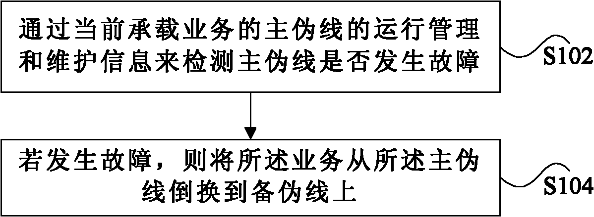
[0023] figure 1 It is a preferred flowchart of a method for protecting a packet transport network according to an embodiment of the present invention, which includes the following steps:
[0024] S102. Detect whether the main PW is faulty through the operation management and maintenance OAM information of the main pseudo-wire PW currently carrying the service;
[0025] S104. If a failure occurs, switch the service from the active PW to the standby PW.
[0026] In this preferred embodiment, TMC (T-MPLS Channel) channel layer protection (PW protection) is used to realize the method of PTN network dual-homing. PW protection refers to providing a backup PW for a specific PW. When the PW occurs In the event of a failure, services can be quickly switched to the standby PW. By switching the service on the failed main pseudo wire (Pseudo Wire, PW for short) to the backup pseudo wire, the problem that the UNI side and the PE node of the PTN network cannot be protected in the prior ar...
Embodiment 2
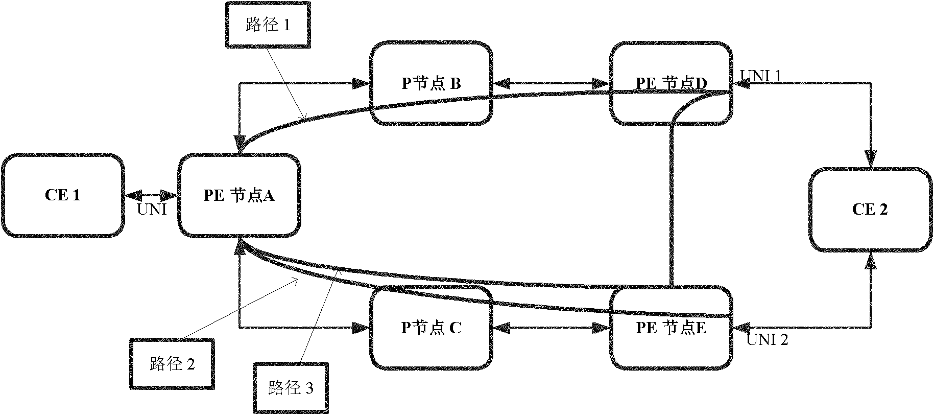
[0035] figure 2It is a schematic diagram of a dual-homing network of a PTN with linear protection according to an embodiment of the present invention, wherein, dual-homing (Dual Homing) is a network topology, in which a device uses an independent access point (attachment point ) is connected to the network, in addition, one access point is the main connection and the other is a backup connection, which is activated in case the main connection fails.
[0036] exist figure 2 Among them, path 1 is the primary PW channel, path 2 is the backup PW channel, and path 3 is the protection path of the primary PW. Different PWs can be used to carry services in different situations. For example, you can refer to the following table to select a PW to carry services:
[0037] Table 1 PWs carrying services in different states of active and standby PWs
[0038]
[0039] In this preferred embodiment, a linear protection method is adopted. Specifically, the service protection method in ...
Embodiment 3
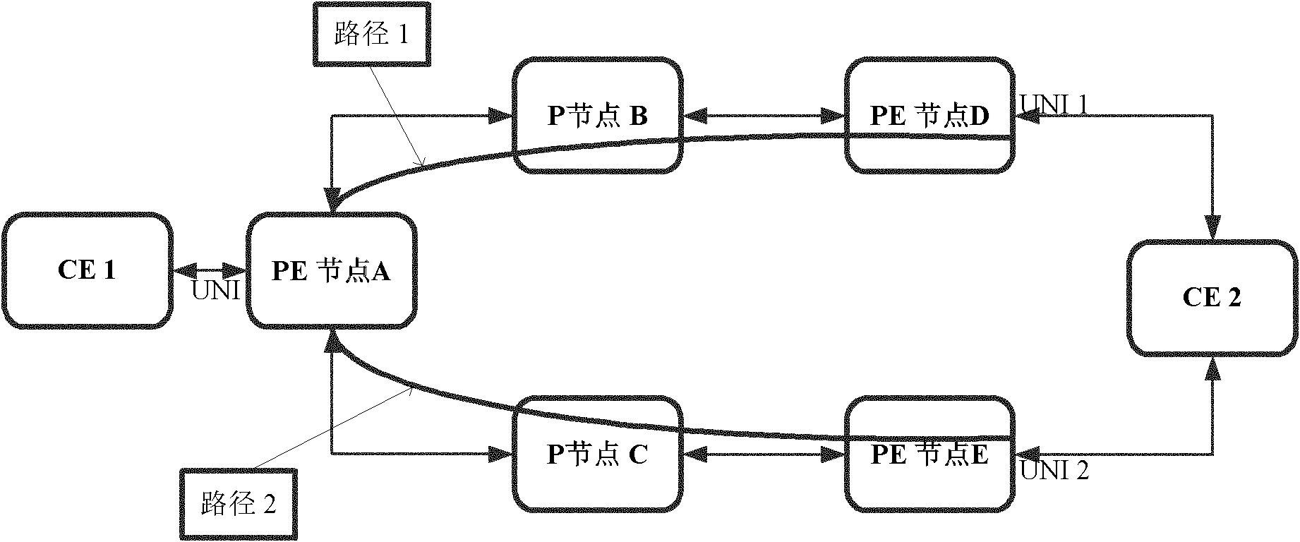
[0047] image 3 is a schematic diagram of a dual-homing network of a PTN without linear protection according to an embodiment of the present invention. image 3 Among them, path 1 is the primary PW channel, and path 2 is the backup PW channel.
[0048] In this preferred embodiment, a non-linear protection method is adopted. Specifically, the service protection method in various situations based on PTN includes the following steps:
[0049] S1: Establish a two-way PW connection channel between PE node A and PE node D (via P node B), take path 1; establish a backup two-way PW connection channel between PE node A and PE node E (via P node B) P node C), take path 2;
[0050] S2: When path 1, path 2, UNI 1, and UNI 2 are all normal, the service goes through path 1 inside the PTN;
[0051] S3: When UNI 1 or PE node D fails, or path 1 fails, the main PW is in SF at this time, and the service is switched to the backup PW, and path 2 and UNI 2 are used;
[0052] S4: When UNI 2 fai...
PUM
 Abstract
Description
Claims
Application Information