
Mixed gas separation, mass storage, pressure rise and energy storage device and method and utility system

A mixed gas, condensation separation technology, used in steam engine installations, refrigeration and liquefaction, compressors, etc., can solve problems such as high investment and operation costs, difficulties in oil-fired power plants, and few qualified caves

Active Publication Date: 2016-02-03
江洪泽
View PDF5 Cites 14 Cited by
  • Summary
  • Abstract
  • Description
  • Claims
  • Application Information

AI Technical Summary

Problems solved by technology

However, there are relatively few qualified rock caves, which limits the promotion of this technology.
Twenty megapascals; thirty megapascals; forty megapascals, high-pressure tank air energy storage technology, liquefied air energy storage technology, supercritical air energy storage technology, still in the experimental or demonstration stage, not yet commercialized or the prospect is unknown
CO2 gas is collected separately, which consumes a lot of energy, and the investment and operation costs are very high
This brings difficulties to the construction of gas and oil power stations in water-scarce areas

Method used

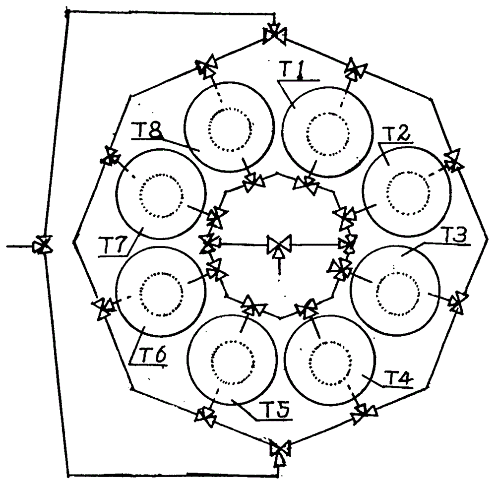
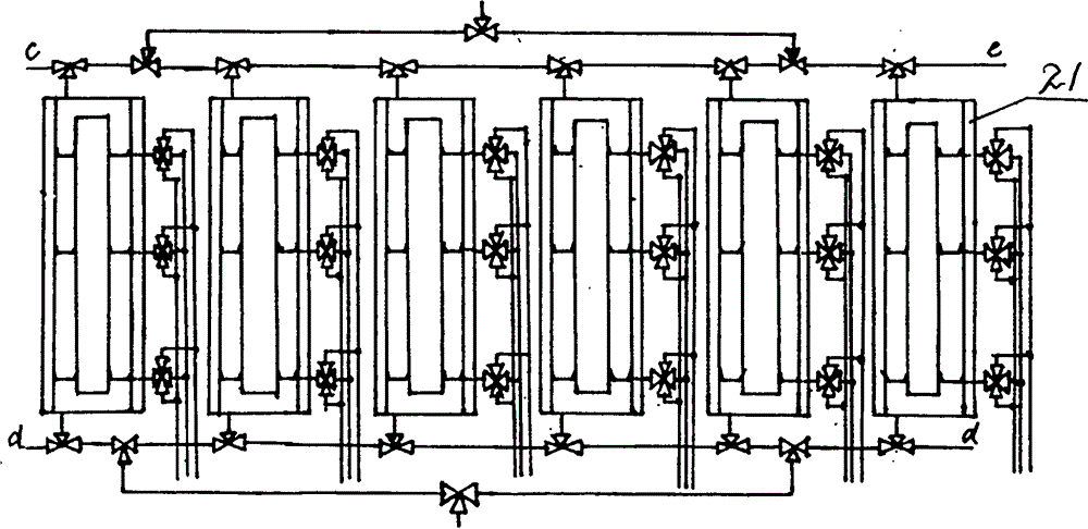
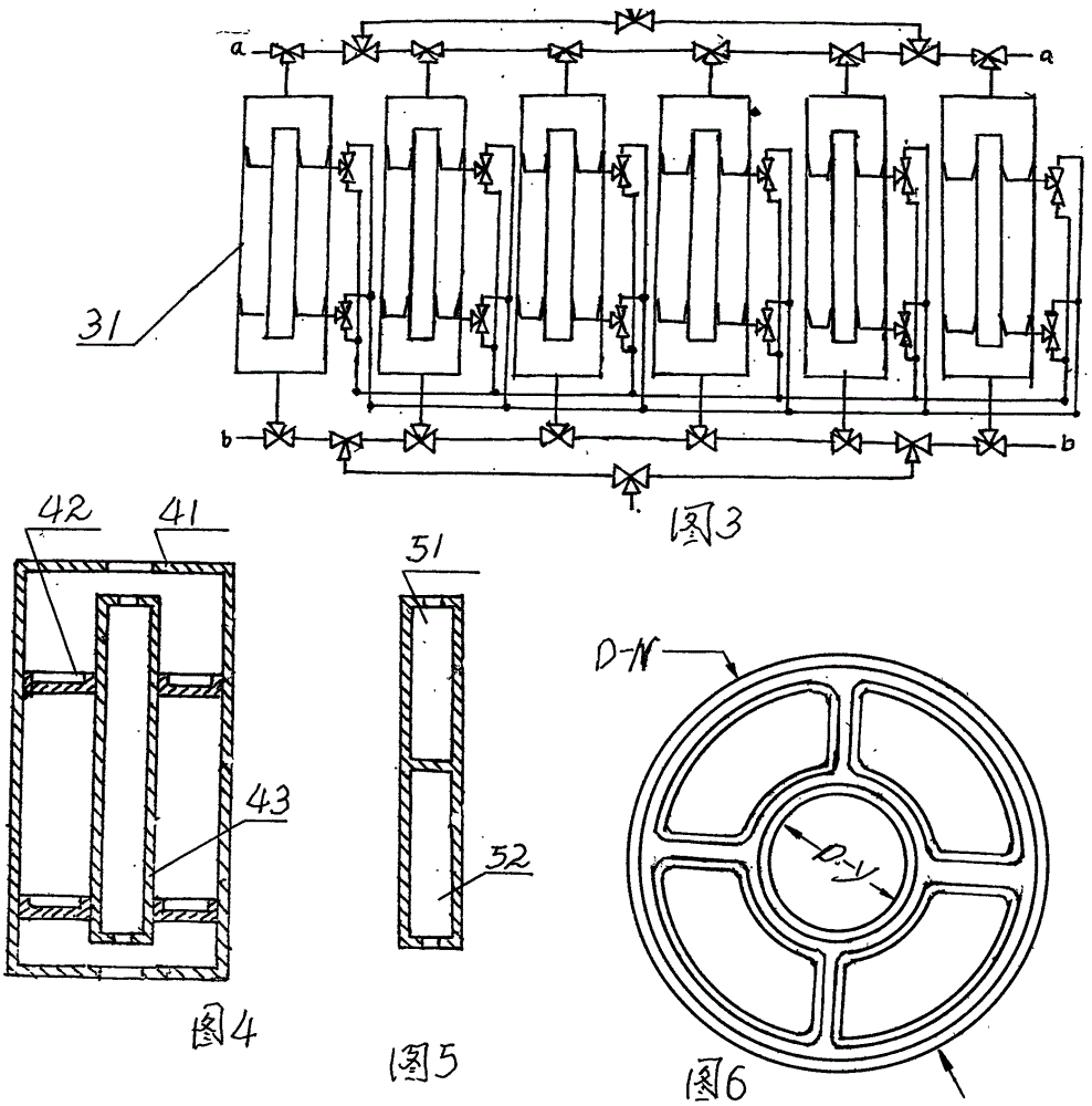

Image

  • Mixed gas separation, mass storage, pressure rise and energy storage device and method and utility system
  • Mixed gas separation, mass storage, pressure rise and energy storage device and method and utility system
  • Mixed gas separation, mass storage, pressure rise and energy storage device and method and utility system

Examples


Embodiment Construction

[0063] Wind Power Plant Air Separation Energy Storage Power Station

[0064] When the wind power plant has excess electric energy, the electric energy is input to the air separation energy storage power station, which is supplied to the motor to drive the compressor (31) to realize the energy storage task. When the peak power consumption comes, the air separation energy storage power station generates electricity and transmits it to the power grid . When the grid fails, the air energy storage power station can quickly provide power support for the grid within a few milliseconds and protect the safe operation of the grid.

[0065] Photovoltaic power plant Air separation energy storage power station

[0066] When the photovoltaic power plant has excess electric energy, the electric energy is input to the air separation energy storage power station, which is supplied to the electric motor to drive the compressor (31) to realize the energy storage task. When the power grid fails...


PUM


Abstract

The invention belongs to the field of energy storage, and discloses a mixed gas separation, mass storage, pressure rise and energy storage device and a method and a utility system, and a heat exchange pressure equalizer. The separation of mixed gas, the pressure rise, the energy storage, the heat exchange and the conversion of gas and liquid are finished in one device, so that the equipment is simplified, the efficiency is improved, and the heat energy is reduced; the cold energy is lost; the energy storage and the energy release can be separately or synchronously performed, so that the emission of carbon dioxide is reduced; and a nitrogen oxide, a sulfur oxide, heavy metal [pm 2.5] and the like are collected for storage and utilization to change harmful substances to useful substances. The invention discloses a gas (air and smoke) condensation, separation and energy storage power station, a wind-electricity plant air separation and energy storage power station, a photovoltaic power generation plant air separation and energy storage power station, a solar heat power air energy storage power station, a wind-electricity solar heat power complementary air energy storage power station, a nuclear power air separation and energy storage power station, a ire coal combustion biomass power generation plane smoke separation and energy storage power station, a gas power generation smoke separation and energy storage power station and an industrial kiln smoke separation and energy storage power station.

Description

technical field [0001] The invention belongs to the field of energy storage, especially the field of gas condensation separation, energy storage, power generation or power drive. Background technique [0002] Mixed gases such as air; natural gas; gas; oilfield gas; flue gas; coal gas; shale gas; coal-to-hydrogen; natural gas-to-hydrogen; The method and technology, the commonly used condensation separation technology, often consumes more energy and needs energy-saving improvement. [0003] Due to the volatility of wind power and solar power, coal power and nuclear power require energy storage devices due to frequent changes in power loads. Pumped water and livestock power stations are the earliest mature technical solutions adopted by countries all over the world. The power station has high requirements on geological conditions and water quality conditions, and it will occupy a large amount of land and relocate people, so site selection is very difficult. Battery energy sto...

Claims


Application Information

Patent Timeline
IPC IPC(8): F25B9/00F01K27/02F01K23/12
Inventor 江洪泽
Owner 江洪泽
Learn More