
Protective relay

A technology for protecting relays and voltages, which is used in emergency protection circuit devices, protections that respond to overvoltage, and emergency protection devices that automatically disconnect. And other issues

Inactive Publication Date: 2012-05-23
KK TOSHIBA
View PDF8 Cites 6 Cited by
  • Summary
  • Abstract
  • Description
  • Claims
  • Application Information

AI Technical Summary

Problems solved by technology

[0005] However, in the contact input circuit using the conventional current-limiting resistor method, the power consumption of resistors connected in series to adjust the threshold voltage increases, causing the temperature of the device to rise.
In addition, it is difficult to use a contact input circuit to adjust the threshold voltage under a wide range of input voltages because the resistance is used to adjust the forward current value of the optocoupler.
Therefore, when it is desired to set a plurality of threshold voltages in a wide range with one contact input circuit, the threshold voltage cannot be adjusted only by changing the resistance constant.
[0006] In addition, in the scheme of Patent Document 1, since the switching element is turned on only when the output of the photocoupler is read, the heat generated by the current limiting resistor can be reduced, but it is difficult to adjust a wide range with a single contact input circuit. Threshold Voltage at Input Voltage
In addition, in the proposal of Patent Document 2, since a bypass current circuit is provided, although a single contact input circuit can be used to adjust the threshold voltage under a wide range of input voltages, the circuit configuration becomes complicated.

Method used


Image

  • Protective relay
  • Protective relay
  • Protective relay

Examples


Embodiment Construction

[0012] Embodiments of the present invention will be described below.

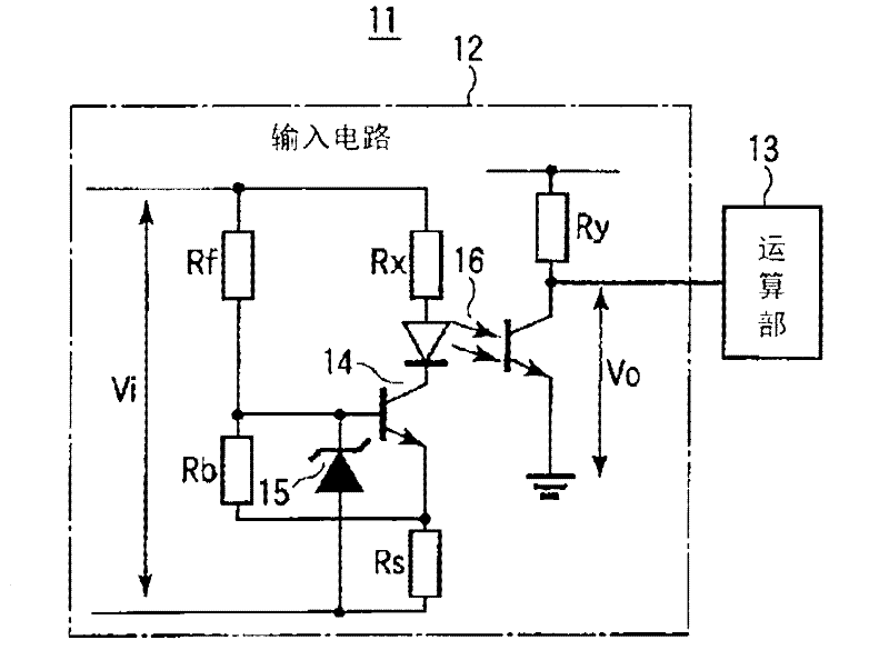
[0013] figure 1 It is a configuration diagram of the protective relay according to the first embodiment of the present invention. The protective relay 11 includes: an input circuit 12 for detecting the state of an external device; and a calculation unit 13 for taking in a detection signal detected by the input circuit 12 and performing a protective relay calculation.

[0014] The input circuit 12 is a circuit for detecting the state of the external device according to whether the external input voltage Vi is greater than a preset threshold voltage. An external input voltage Vi representing the state of the external device is input between the positive and negative lines of the input circuit 12 and divided by resistors Rf, Rb, and Rs. Furthermore, the divided voltage at the connection point of the voltage dividing resistors Rf and Rb is input to the base of the transistor serving as the switching means 14 ...


PUM


Abstract

There are included an input circuit (12) that determines whether an external input voltage is greater than a predetermined threshold voltage, thereby detecting the status of an external device; and an calculating unit (13) that acquires an detection signal, which is obtained by the detection of the input circuit (12), and performs a protective relay calculation. The input circuit (12) includes: a switching means (14) that, when the external input voltage is equal to or greater than the threshold voltage, is rendered conductive by a partial voltage obtained by voltage dividing resistors that divide the external input voltage; and a photocoupler (16) that is rendered operative by a constant current of a constant current output circuit, which supplies the constant current when the switching means (14) is rendered conductive, and that outputs an operation signal to the calculating unit (13).

Description

technical field [0001] Embodiments of the present invention relate to a protective relay having an input circuit that detects the state of an external device based on whether an external input voltage is greater than a preset threshold voltage. Background technique [0002] For example, the protection relays that protect the power system detect system accidents through input current, input voltage, phase relationship, etc., and perform protection control calculations to protect the power system. In this case, the state of the external device is input using a contact input signal, for example, a contact input (Binary Input) is detected by the magnitude of the external input voltage value relative to a predetermined threshold voltage. [0003] In conventional contact input circuits, the resistors connected in series or in parallel to the photocoupler as current limiting resistors adjust the current value flowing through the photocoupler and set the threshold voltage to realize...

Claims


Application Information

Patent Timeline
IPC IPC(8): H02H3/02H03K17/78
CPCH02H3/02H02H3/20H03K17/7955H02H1/0007
Inventor 白川纮之柳桥佑亮前原宏之田中年男须贺纪善首藤逸生
Owner KK TOSHIBA
Learn More