Unlock instant, AI-driven research and patent intelligence for your innovation.

Method of controlling a variable speed constant frequency generator

一种控制方法、发电机的技术,应用在发电机控制电路、发电机的频率和电压控制、控制发电机等方向

Inactive Publication Date: 2012-05-23
GENERAC POWER SYST INC
View PDF4 Cites 7 Cited by
  • Summary
  • Abstract
  • Description
  • Claims
  • Application Information

AI Technical Summary

Problems solved by technology

In addition, an engine-driven generator operating at its intended operating speed produces unwanted noise
It can be expected that reducing the operating speed of the generator's engine for a given load will reduce the noise associated with the operation of the engine-driven generator

Method used


Image

  • Method of controlling a variable speed constant frequency generator
  • Method of controlling a variable speed constant frequency generator

Examples


Embodiment Construction

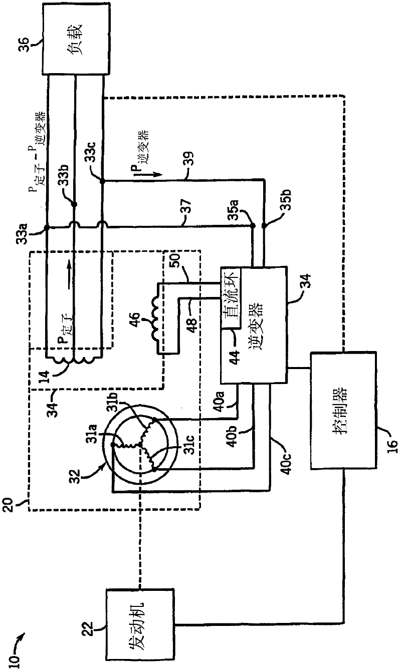
[0019] refer to figure 1 , an engine-driven generator system for carrying out the method of the invention is indicated generally by reference numeral 10 . Generator system 10 includes a generator 20 defined by a cylindrical rotor 30 rotatably received within a stator 32 . By way of example, rotor 30 includes three-phase windings 31a-31c powered by an inverter 34, as described below. The stator 32 includes a plurality of electrical windings, such as the main winding 14 , coiled on an iron core, and a field or quadrature winding 46 offset 90 degrees from the main winding 14 . Rotation of the rotor 30 produces a moving magnetic field around the stator 32 which in turn induces a voltage difference between the windings of the stator 32 . Thus, the outputs 33a-33c across the stator 32 provide alternating current (AC) power. The outputs 33a-33c of the stator 32 may be connected to a load 36 to provide AC power thereto.

[0020] The generator system 10 also includes an engine 22 ....


PUM


Abstract

A method of controlling an engine-driven, electrical generator is provided. The generator generates an output voltage at a frequency with the engine running at an operating speed. The method includes the steps of connecting the generator to a load and varying the operating speed of the engine to optimize fuel consumption in response to the load. Thereafter, the frequency of the output voltage is modified to a predetermined level.

Description

technical field [0001] The invention generally relates to a generator driven by an engine, and in particular to a control method for a standby generator with variable speed and constant frequency. Background technique [0002] Generators are used in a wide variety of applications. Typically, each generator operates in a standby mode in which the power supplied by the utility is monitored so that if commercial power from the utility fails, the generator's engine is automatically started causing the alternator to generate power. When the power generated by the alternator reaches a predetermined voltage and frequency desired by the customer, the transfer switch transfers the load applied by the customer from the commercial power line to the generator. [0003] Typically, generators use a single drive motor connected to a generator or alternator via a common shaft. When the engine is started, the crankshaft rotates the common shaft, which drives the alternator, which in turn g...

Claims


Application Information

Patent Timeline
Patent Type & Authority Applications(China)
IPC IPC(8): H02P9/44
CPCH02P9/04H02P9/007H02P9/42
Inventor 格拉汉姆·W·麦克莱恩大卫·波洛克弗朗西斯·X·威德尔
Owner GENERAC POWER SYST INC
Features
  • R&D
  • Intellectual Property
  • Life Sciences
  • Materials
  • Tech Scout
  • Unparalleled Data Quality
  • Higher Quality Content
  • 60% Fewer Hallucinations
Learn More