

Dynamic-pressure bearing stable in oil supply
A dynamic pressure bearing, a stable technology, applied in the field of dynamic pressure bearings, can solve the problems of easy oil being thrown out of the oil chamber, bearing vibration, insufficient oil volume in the oil chamber, etc., and achieve the effect of stable oil volume and small vibration
Inactive Publication Date: 2012-05-30
DALIAN CHUANGDA TECH TRADE MARKET
View PDF0 Cites 1 Cited by
- Summary
- Abstract
- Description
- Claims
- Application Information
AI Technical Summary
Problems solved by technology
[0002] The dynamic pressure bearing uses the hydraulic oil to be compressed in the wedge-shaped oil chamber between the rotating shaft and the bearing sleeve to generate pressure. The faster the rotating shaft rotates, the greater the pressure of the hydraulic oil, while the oil in the existing oil chamber is directly from the It enters between the rotating shaft and the bearing sleeve. When the rotating shaft rotates at high speed, the oil is easily thrown out of the oil chamber due to the centrifugal force when the rotating shaft rotates at high speed, which will cause insufficient oil in the oil chamber and cause the bearing to vibrate.
Method used
View moreImage
Smart ImageViewing Examples

Examples
Embodiment Construction
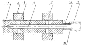
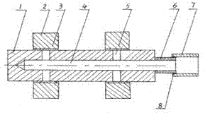
[0010] Such as figure 1 As shown, a dynamic pressure bearing includes a rotating shaft 1 and a shaft sleeve 2. There is a wedge-shaped oil chamber 3 between the rotating shaft 1 and the shaft sleeve 2. It is characterized in that there is a central oil hole 4 in the center of the rotating shaft 1. There is a vertical oil hole 5 perpendicular to the shaft centerline at the position corresponding to the rotary shaft 1 and the wedge-shaped oil chamber 3. The vertical oil hole 5 communicates with the central oil hole 4. A rotary oil pipe 6 is installed at the position of the central oil hole 4 at one end of the rotary shaft. Oil pipe 6 is contained in the fixed oil pipe 7, and sealing ring 8 is housed in the middle.
Login to View More PUM
 Abstract
The invention belongs to a dynamic-pressure bearing stable in oil supply, which comprises a rotary shaft and shaft sleeves. Wedged oil cavities are formed among the rotary shaft and the shaft sleeves. The dynamic-pressure bearing is characterized in that t a center oil hole is arranged in the axial center of the rotary shaft, and perpendicular oil holes perpendicular to the axial center line of the rotary shaft are arranged on the rotary shaft, correspond to the wedged oil cavities and are communicated with the center oil hole. A rotary oil pipe is arranged at the center oil hole at one end of the rotary shaft and is mounted in a fixed oil pipe, and a sealing ring is mounted in the middle of the rotary oil pipe. Pressure oil enters the center oil hole from the fixed oil pipe through the rotary oil pipe and then flows into the oil cavities through the perpendicular oil holes. When the rotary shaft rotates, the pressure oil can be thrown to the oil cavities from the center oil hole through the perpendicular oil holes under the action of centrifugal force, accordingly, stable oil supply for the oil cavities at high speed can be guaranteed, the oil quantity of the oil cavities of the dynamic-pressure bearing is stable, and vibration of the dynamic-pressure bearing is low.
Description
technical field [0001] The invention belongs to the category of mechanical manufacturing, in particular to a dynamic pressure bearing with stable oil supply. Background technique [0002] The dynamic pressure bearing uses the hydraulic oil to be compressed in the wedge-shaped oil chamber between the rotating shaft and the bearing sleeve to generate pressure. The faster the rotating shaft rotates, the greater the pressure of the hydraulic oil, while the oil in the existing oil chamber is directly from the When the rotating shaft rotates at a high speed, the oil is easily thrown out of the oil chamber due to the centrifugal force, which will cause insufficient oil in the oil chamber and cause the bearing to vibrate. Contents of the invention [0003] The object of the present invention is to provide a dynamic pressure bearing with stable oil supply in view of the deficiencies in the prior art. [0004] Technical scheme of the present invention is as follows: [0005] A d...
Claims
Login to View More Application Information
Patent Timeline
 IPC IPC(8): F16C17/12
Inventor王爽
OwnerDALIAN CHUANGDA TECH TRADE MARKET