
Optical-fiber network node terminal and passive optical-fiber network (PON) system

An optical network node and passive optical network technology, applied in the field of optical network node ONU terminals and passive optical network PON systems, can solve the problems of difficult to replace serial ports, increasing the number of backbone communication cables, and easily limited transmission distances.

Inactive Publication Date: 2012-05-30
ZTE CORP
View PDF6 Cites 4 Cited by
  • Summary
  • Abstract
  • Description
  • Claims
  • Application Information

AI Technical Summary

Problems solved by technology

[0002] In the field of industrial control applications, traditional serial communication is widely used. However, traditional serial communication has problems such as signal cables are easily interfered, transmission distance is easily limited, and multiple serial ports work at the same time will increase the number of backbone communication cables. The demand for signal transmission in the control field, but because of its wide application, the serial port is difficult to replace in a short time

Method used


Image

  • Optical-fiber network node terminal and passive optical-fiber network (PON) system
  • Optical-fiber network node terminal and passive optical-fiber network (PON) system
  • Optical-fiber network node terminal and passive optical-fiber network (PON) system

Examples


Embodiment Construction

[0019] Hereinafter, the present invention will be described in detail with reference to the drawings and examples. It should be noted that, in the case of no conflict, the embodiments in the present application and the features in the embodiments can be combined with each other.

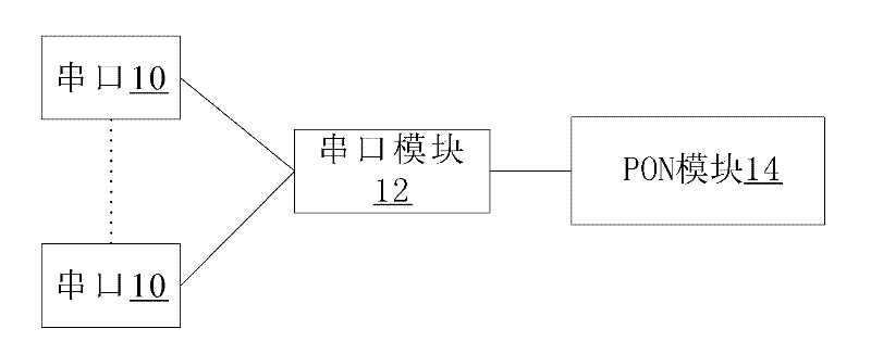
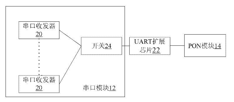
[0020] figure 1 It is a structural block diagram of an ONU terminal according to an embodiment of the present invention. like figure 1 The shown ONU terminal includes: one or more serial ports 10; PON module 14; 10 to transfer data between.

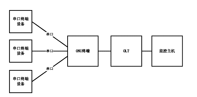
[0021] Through the above-mentioned terminal, the serial port passive optical network device connection is realized, and the optical communication bearer of the serial port is realized. Passive optical network equipment has the advantages of long transmission distance, low interference of optical communication, and large bandwidth. These advantages are introduced through the above-mentioned terminal, which has certain advantages compared with traditional seri...


PUM


Abstract

The invention discloses an optical-fiber network node terminal and a passive optical-fiber network (PON) system. The optical-fiber network node terminal comprises one or more serial ports, a PON module and a serial port module, wherein the serial port module is connected with the PON module and one or more serial ports and is used for the data transmission between the PON module and the one or more serial ports. Due to the adoption of the optical-fiber network node terminal and the PON system, the problem of the traditional serial port communication can be solved, and the optical communication carrying of the serial port can be realized.

Description

technical field [0001] The invention relates to the communication field, in particular to an optical network node ONU terminal and a passive optical network PON system. Background technique [0002] In the field of industrial control applications, traditional serial communication is widely used. However, traditional serial communication has problems such as signal cables are easily interfered, transmission distance is easily limited, and multiple serial ports work at the same time will increase the number of backbone communication cables. The need for signal transmission in the control field, but because of its wide application, the serial port is difficult to replace in a short time. Contents of the invention [0003] The main purpose of the present invention is to provide an optical network node ONU terminal and a passive optical network PON system to at least solve one of the above problems. [0004] According to one aspect of the present invention, an optical network ...

Claims


Application Information

Patent Timeline
Patent Type & Authority Applications(China)
IPC IPC(8): H04Q11/00H04B10/272
CPCH04Q2011/0079H04Q11/0067H04B10/272
Inventor 张海军马小松金国华
Owner ZTE CORP
Learn More