U-shaped nail symmetric punching and positioning mechanism

A positioning mechanism and symmetrical technology, which is applied in the field of U-shaped nail symmetrical stamping positioning mechanism and the device for manufacturing U-shaped nails, can solve the problems of high and low feet, and achieve the effect of improving quality

Inactive Publication Date: 2012-06-06
SHANGHAI GORO CONVEYOR EQUIP CO LTD
View PDF5 Cites 7 Cited by
  • Summary
  • Abstract
  • Description
  • Claims
  • Application Information

AI Technical Summary

Problems solved by technology

[0003] The purpose of the present invention is to provide a U-shaped nail symmetrical punching positioning mechanism, said U-shaped nail symmetrical punching positioning mechanism to solve the technical problem of high and low feet that are prone to occur when punching U-shaped nails in the prior art

Method used


Image

  • U-shaped nail symmetric punching and positioning mechanism
  • U-shaped nail symmetric punching and positioning mechanism
  • U-shaped nail symmetric punching and positioning mechanism

Examples


Embodiment Construction

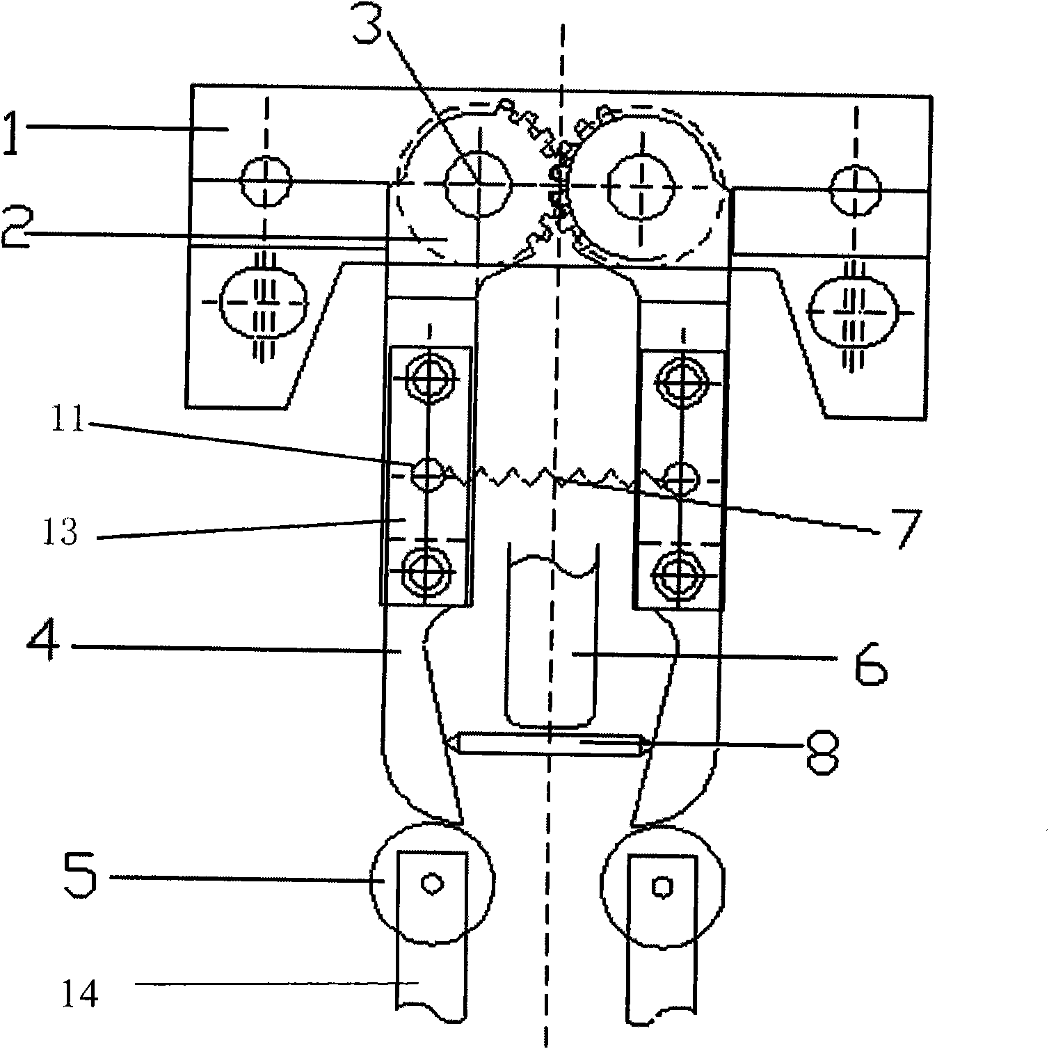
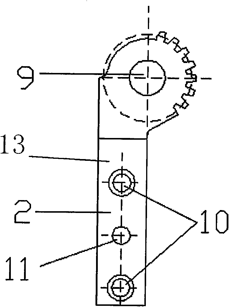
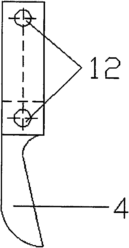
[0012] Such as figure 1 , figure 2 and image 3 As shown, a U-shaped nail symmetrical stamping positioning mechanism of the present invention is composed of a gear seat 1, wherein two positioning devices are symmetrically arranged in the gear seat 1, and any one of the positioning devices is respectively positioned by a Arm 13 and a support seat 14 constitute, and the upper end of any one described positioning arm 13 is all fixedly provided with a gear 2, and the described gear 2 of two positioning arms 13 upper ends meshes with each other, and the center of circle of any one gear 2 is Gear holes 9 are provided, and any one of the gear holes 9 is provided with a gear shaft 3, and any one of the gear shafts 3 is arranged in the gear seat 1, and the symmetrical positions of the positioning arms 13 in the two positioning devices A spring 7 is connected between them, and the lower end of any positioning arm 13 is provided with a fork 4, and the opposite sides of the fork 4 in t...


PUM


Abstract

The invention relates to a U-shaped nail symmetric punching and positioning mechanism which comprises gear seats; two positioning devices are symmetrically arranged in the gear seats; any one positioning device respectively comprises a positioning arm and a support seat; the upper end of the positioning arm is fixedly provided with a gear; the gears on the upper ends of the two positioning arms are mutually engaged; the gears are arranged in the gear seats through gear shafts; a spring is connected between the symmetric positions of the two positioning arms; the lower ends of the positioning arms are provided with shifting forks; the opposite side surfaces of the two shifting forks are in oblique surface shapes; the lower ends of the shifting forks are in arc-shaped surface shapes; the upper ends of the support seats are respectively provided with a roller through a connecting shaft; and the outer peripheries of the rollers are respectively tangential to the arc-shaped surfaces of the shifting forks above the rollers. According to the U-shaped nail symmetric punching and positioning mechanism, the two positioning devices which are symmetrically arranged adjust a central point of a U-shaped nail to be processed to a punching central path of a punch, so that the pin height is kept consistent when in formation, and the product quality is improved.

Description

Technical field: [0001] The invention relates to the field of machinery, in particular to a device for manufacturing U-shaped nails by a stamping method, in particular to a symmetrical stamping and positioning mechanism for U-shaped nails. Background technique: [0002] In the prior art, when the U-shaped nails are manufactured by stamping, the punch is directly aligned with the middle of the U-shaped nails for punching, which cannot ensure that the punching point is located at the symmetrical center of the U-shaped nails, and the U-shaped nails are prone to high and low feet after punching . Invention content: [0003] The object of the present invention is to provide a U-shaped nail symmetrical punching and positioning mechanism. The U-shaped nail symmetrical punching and positioning mechanism is to solve the technical problem that high and low feet are easy to occur when punching U-shaped nails in the prior art. [0004] The U-shaped nail symmetrical stamping positioni...

Claims


Application Information

Patent Timeline
Patent Type & Authority Applications(China)
IPC IPC(8): B21D53/46B21D43/00
Inventor 封心浩陆俭贺洪华
Owner SHANGHAI GORO CONVEYOR EQUIP CO LTD
Why Eureka
Try Eureka