Gasification oil burner

A gasifier and burner technology, applied in the direction of burner, combustion method, combustion type, etc., can solve the problems of large atomization particle size, insufficient combustion, waste of energy, etc., and achieve high combustion efficiency, low cost, and high combustion effect Good results

Active Publication Date: 2014-08-20
YANTAI LONGYUAN POWER TECH
View PDF8 Cites 0 Cited by
  • Summary
  • Abstract
  • Description
  • Claims
  • Application Information

AI Technical Summary

Problems solved by technology

[0003] When the ordinary mechanical atomization fuel oil method is started in the cold furnace, due to the large output, the nozzle aperture is larger than 5mm. At this time, the atomization particle size is relatively large, and the oil mist is distributed in a horseshoe shape, that is, the oil mist is concentrated in the Near the cone edge of the fog cone at about 80°, there is little oil mist in the center of the fog cone. At this time, the peripheral temperature of the fog cone edge is very low, so the combustion is very insufficient, and black smoke will inevitably be emitted, which is a waste of energy and pollution. surroundings

Method used


Image

  • Gasification oil burner
  • Gasification oil burner
  • Gasification oil burner

Examples


Embodiment Construction

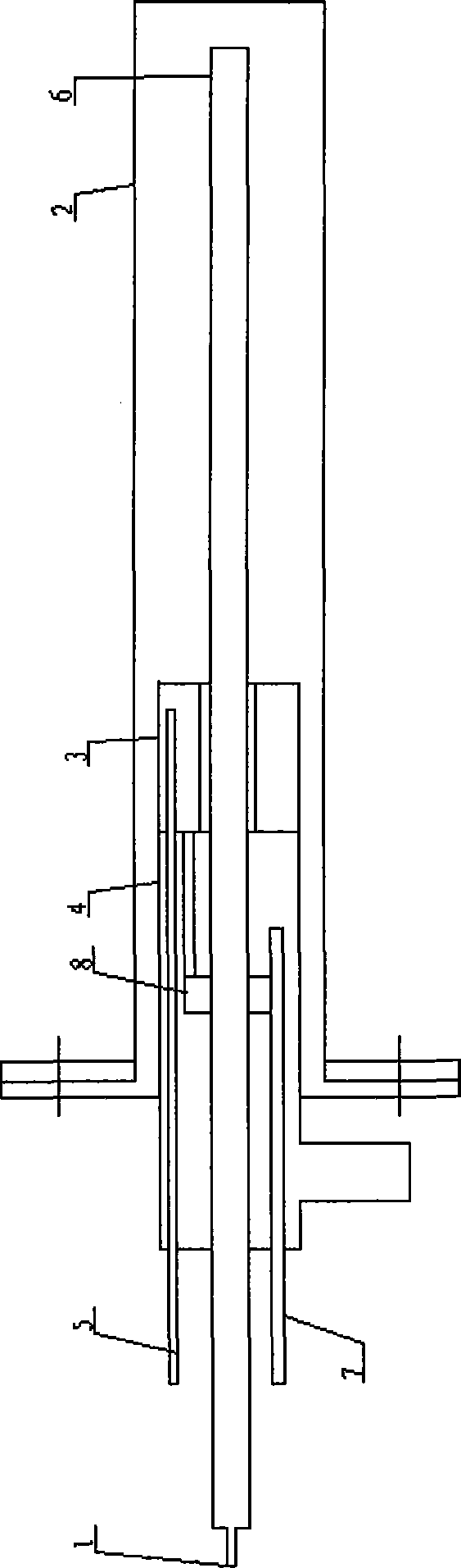
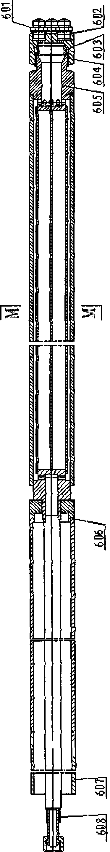
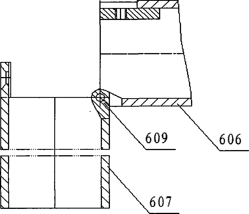
[0032] exist figure 1 Shows the gasification oil burner structure according to one embodiment of the present invention. like figure 1 As shown, the gasification oil burner includes a first-stage gasification flame generator, and the first-stage gasification flame generator includes a gasifier 3, an air distribution tube 4, a gasifier oil inlet pipe 5, an atomizing nozzle 8, Connect gasifier 3 with oil pipe of atomizing nozzle 8, and ignition gun 7. The gasification flame generator of the first stage can of course also consist of only these components. The gasification oil burner can also include a gasification oil gun 6 and a gasification oil gun inlet pipe 1, which constitute a second-stage gasification flame generator.

[0033] The vaporizer 3 is arranged inside the air distribution cylinder 4, preferably connected with the air distribution cylinder 4 as a whole. The gasifier fuel inlet pipe 5 is connected to the gasifier 3 for delivering fuel to the gasifier 3 . The at...


PUM


Abstract

The invention relates to a gasification oil burner, comprising a first-stage gasification flame generator, wherein the first-stage gasification flame generator includes a gasifier (3), an air distribution tube (4), a gasifier inlet oil pipe (5), atomizing nozzle (8) and ignition gun (7), wherein, the gasifier (3) is arranged inside the air distribution cylinder (4), and the gasifier oil inlet pipe (5) is connected with the gasifier (3) is connected to deliver fuel oil to the gasifier (3); the atomizing nozzle (8) is installed in the air distribution tube (4) and is connected with the gasifier (3) through the oil pipe, and the atomizing nozzle ( 8) It is used to atomize and spray the liquid fuel oil from the vaporizer (3) and to spray the vaporized fuel oil from the vaporizer (3); the ignition gun (7) is inserted into the air distribution tube (4), Used to ignite the fuel sprayed by the atomizing nozzle (8). Through the gasification oil burner of the present invention, the gasification combustion of fuel oil is realized to achieve improved fuel combustion efficiency, which not only saves energy but also protects the environment.

Description

technical field [0001] The invention relates to a gasification oil burner. Background technique [0002] For the cold furnace ignition and stable combustion of various types of boilers in various thermal power plants in the electric power industry, the traditional way of ignition is to use atomized fuel oil. [0003] When the ordinary mechanical atomization fuel oil method is started in the cold furnace, due to the large output, the nozzle aperture is larger than 5mm. At this time, the atomization particle size is relatively large, and the oil mist is distributed in a horseshoe shape, that is, the oil mist is concentrated in the Near the cone edge of the fog cone at about 80°, there is little oil mist in the center of the fog cone. At this time, the peripheral temperature of the fog cone edge is very low, so the combustion is very insufficient, and black smoke will inevitably be emitted, which is a waste of energy and pollution. surroundings. [0004] Chinese patent CN2008...

Claims


Application Information

Patent Timeline
Patent Type & Authority Patents(China)
IPC IPC(8): F23D11/00F23D11/38F23D11/44
CPCF23D11/443F23D11/38
Inventor 曹琴李本伟任志鹏邵天成王海鹏
Owner YANTAI LONGYUAN POWER TECH
Why Eureka
Try Eureka