

Feedback microwave antenna
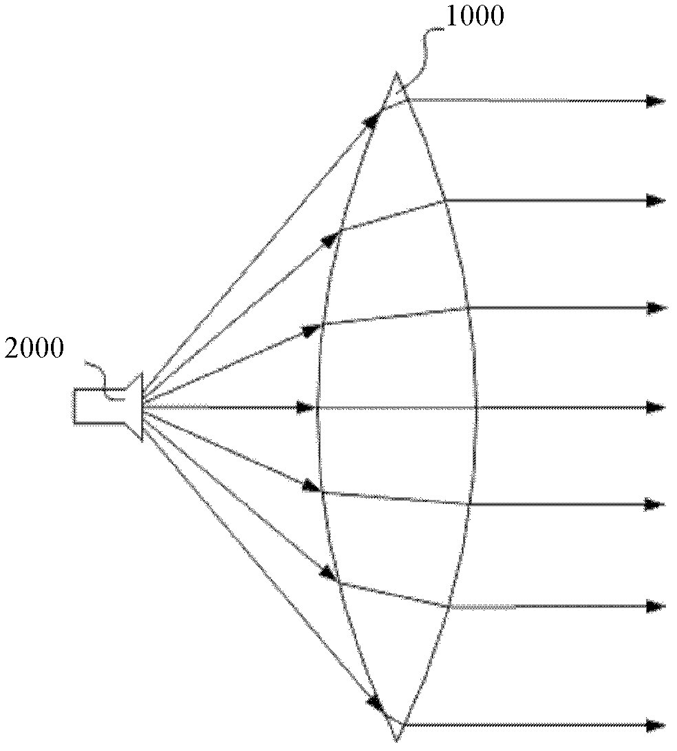
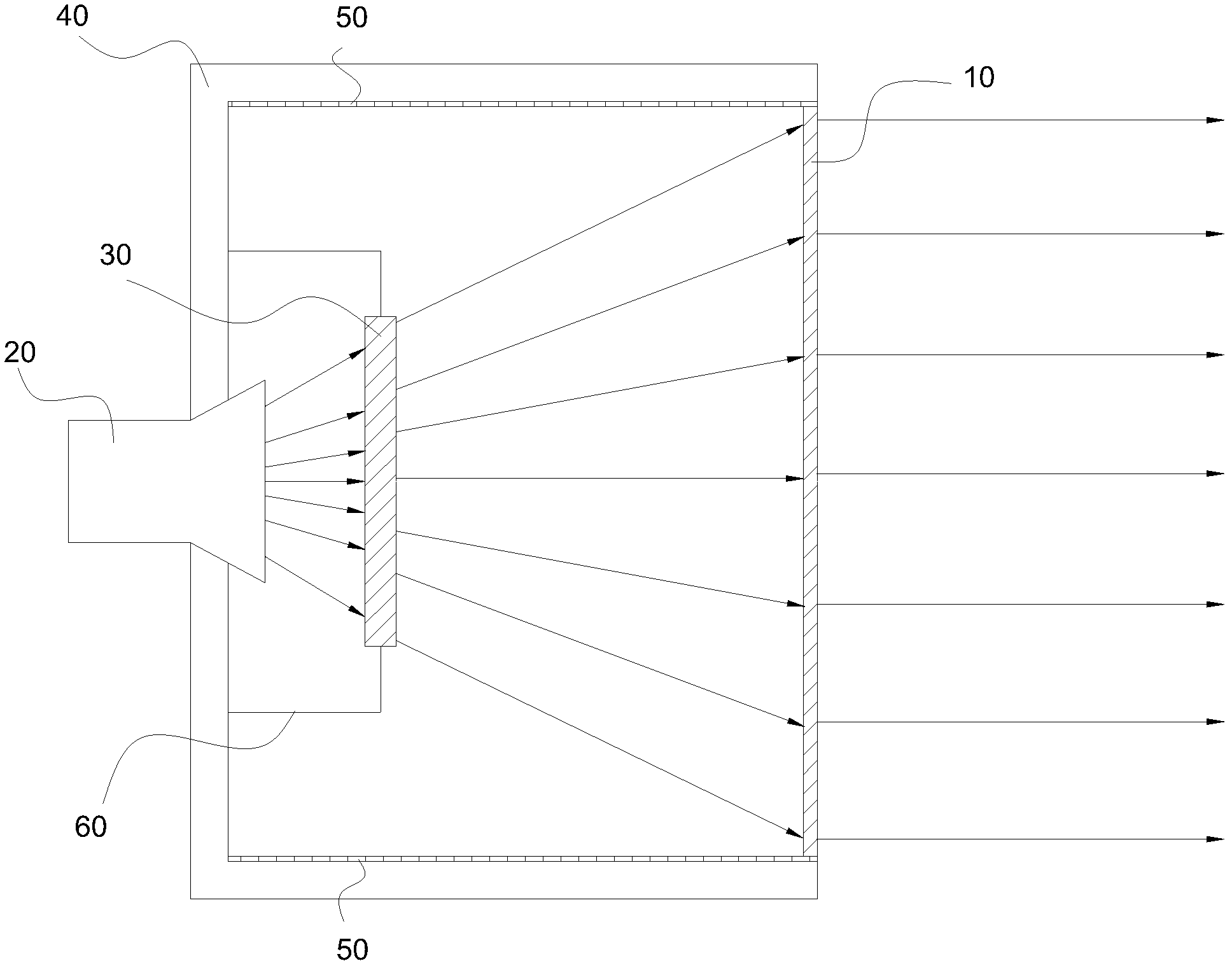
A microwave antenna and feed-type technology, applied in antennas, electrical components, etc., can solve the problems of electromagnetic energy reduction, large spherical lens 1000, electromagnetic wave reflection interference, etc., to avoid the reduction of electromagnetic energy, improve the range of short-distance radiation, The effect of improving antenna performance
- Summary
- Abstract
- Description
- Claims
- Application Information
AI Technical Summary
Problems solved by technology
Method used
Image

Examples
Embodiment Construction
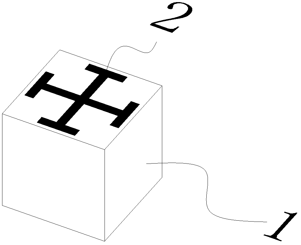
[0031] Light, as a kind of electromagnetic wave, when passing through glass, because the wavelength of the light is much larger than the size of the atom, we can use the overall parameters of the glass, such as the refractive index, instead of the detailed parameters of the atoms that make up the glass. The response of glass to light. Correspondingly, when studying the response of a material to other electromagnetic waves, the response of any structure in the material that is much smaller than the wavelength of the electromagnetic wave to electromagnetic waves can also be described by the overall parameters of the material, such as the dielectric constant ε and the permeability μ. By designing the structure of each point of the material, the dielectric constant and permeability of each point of the material are the same or different, so that the overall dielectric constant and permeability of the material are arranged regularly, and the magnetic permeability and permeability of ...
PUM
 Abstract
Description
Claims
Application Information