
Twist lock device for container hanging tool

A container spreader and twist lock technology, which is applied in the direction of transportation and packaging, load hanging components, etc., can solve the problems of container falling off, hanging boxes, safety accidents, etc.

Inactive Publication Date: 2012-06-13
李怀昌
View PDF14 Cites 6 Cited by
  • Summary
  • Abstract
  • Description
  • Claims
  • Application Information

AI Technical Summary

Problems solved by technology

[0002] The twist lock device of the container spreader is an important stress-bearing part of the container spreader. At present, in the operation practice, there have been accidents where the container fell off during the lifting and handling process, and there have also been accidents where the container cannot be unlocked smoothly.
Some of the reasons for the accident were that the corner fittings of the container could not cooperate well with the twist lock device due to the deformation of the container, and some were also due to the structural defects of the twist lock device itself, for example, it used a flat key to cooperate, but when the flat key matching surface was damaged, it would not It was not discovered in time, and eventually led to the failure of the turn lock to open and lock in place, resulting in safety accidents of unpacking and hanging the box; therefore, the reliability and safety of the turn lock device must be paid attention to during operation.
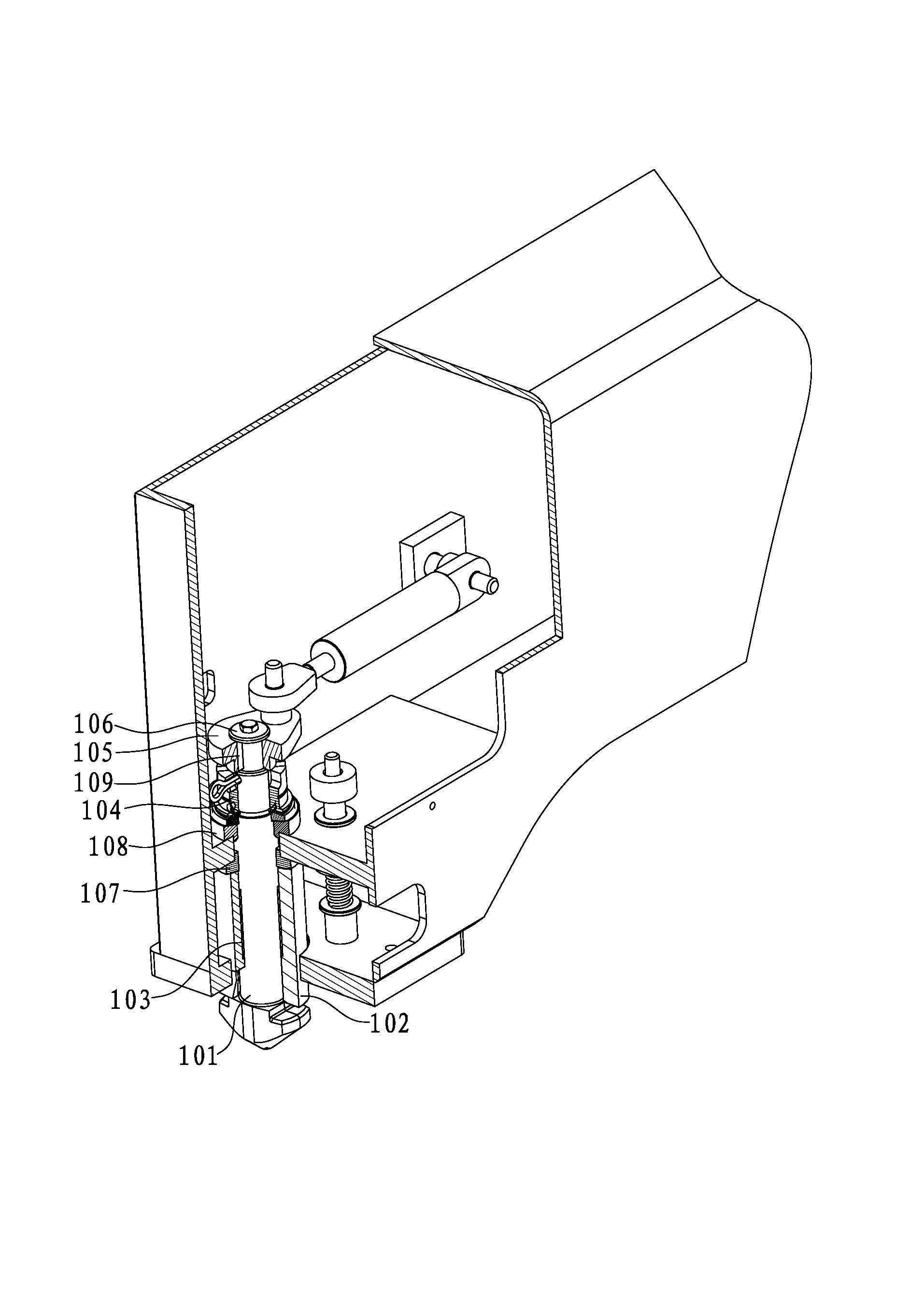
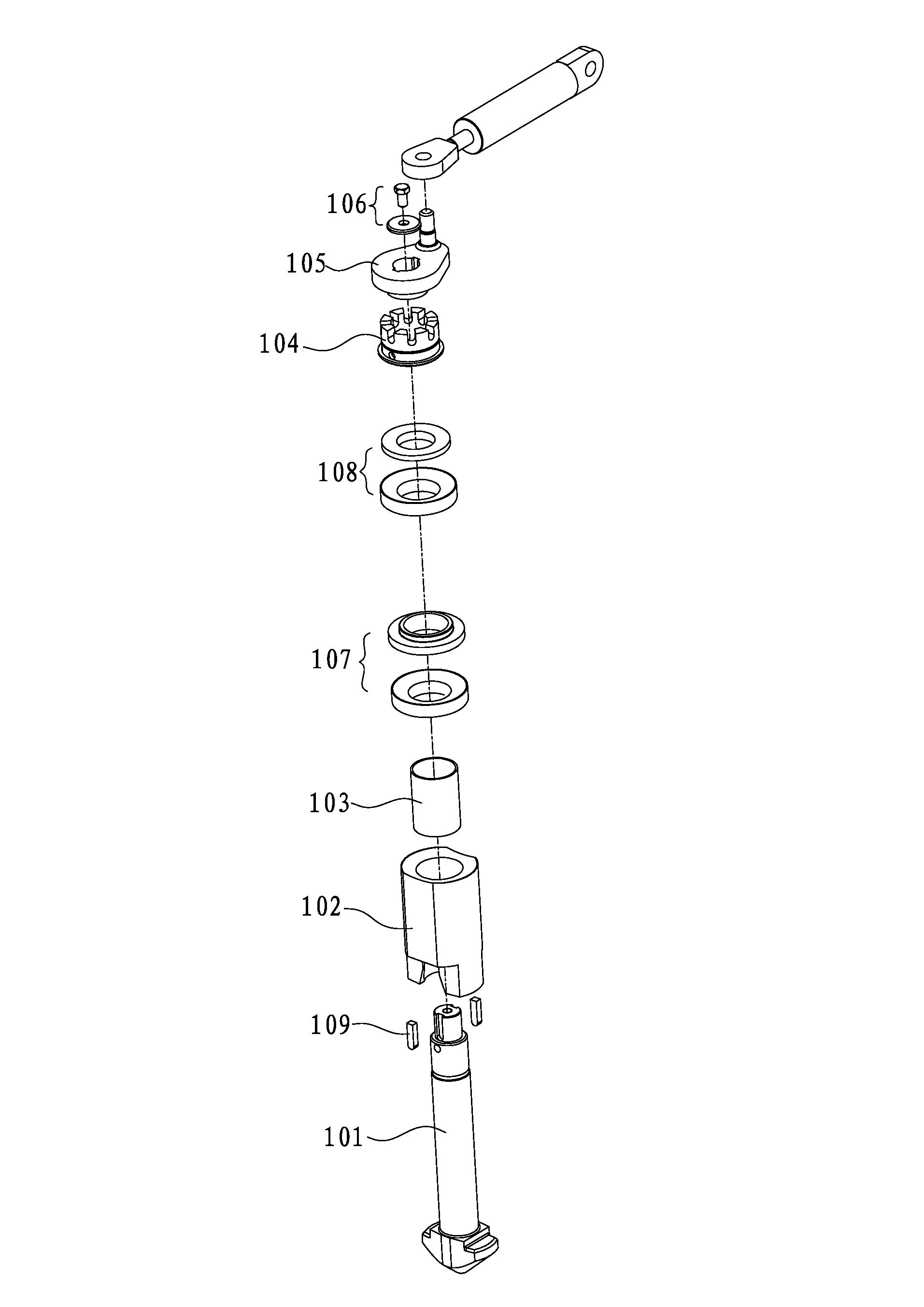
[0003] But, because the rotation push handle and the turn lock pin of the turn lock device in the prior art are connected by a vertical flat key, specifically as figure 1 and Figure 1A As shown, it is a traditional and commonly used turning handle installed on the turning lock nut, which has a turning lock pin 101, a guide bush 102, a lubricating bush 103, a turning lock nut 104, a turning handle 105, an anti-loose Take off part 106, lower spherical surface self-aligning support 107, upper spherical surface self-aligning support 108 and flat key 109; This turn lock pin 101 is the core component of whole turn lock device, and it cooperates with container corner piece; This turn lock pin 101 and The rotating handle 105 is processed to form a keyway on the mating circumferential surface of the two, and is connected together by a flat key 109 to realize torque transmission; in actual use, the flat key 109 installed in the vertical direction corresponds to a pressure fit There is a risk of damage to the surface, but due to the cover of the anti-loosening part 106, the pressure-bearing mating surface cannot be known unless it is disassembled, which is inconvenient for daily inspection and poses a safety hazard
[0004] Although there is research on the twist lock device in the current patent documents, there are still shortcomings that cannot be easily inspected; for example, the Chinese utility model patent ZL01253646.6 discloses a floating turn lock device with a turning handle installed under the turn lock nut , the torque transmission surface of the twist lock device is undoubtedly blocked and cannot be visually discovered by daily inspections. Once the key connection or other connection used by it is damaged, it is very easy to form a safety hazard and cause a safety accident
In addition, the turn lock nut is installed above the turn handle, and the matching keyway between the turn handle and the turn lock pin will inevitably reduce the strength of the turn lock pin slightly.
Another example is Chinese utility model patent ZL200820178750.8, which discloses a turnlock device in which the turnlock pin is designed as a boss. Although the flat key connection installed in the vertical direction is no longer used to transmit torque, the top cover of its design is still The torque transmission mating surface is covered, and once the torque transmission mating surface is damaged, it cannot be easily found

Method used


Image

  • Twist lock device for container hanging tool
  • Twist lock device for container hanging tool
  • Twist lock device for container hanging tool

Examples


no. 1 example

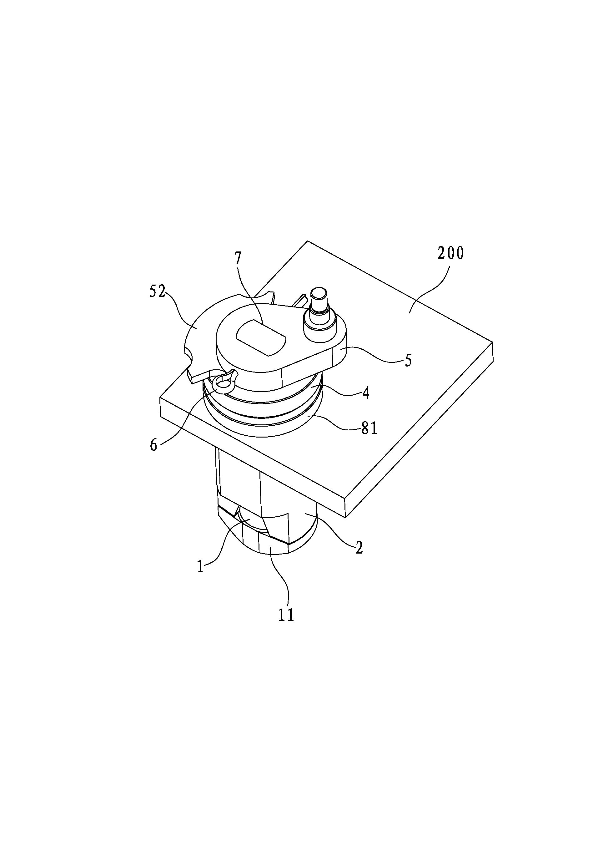
[0047] Such as figure 2 and Figure 2AAs shown, it is the first embodiment of the twist lock device of the present invention related to a container spreader. The turn lock device is installed on the support plate 200 of the container spreader. The turn lock device includes a turn lock pin 1, a guide bushing 2. Lubricating bushing 3, turn lock nut 4, turn handle 5 and anti-loosening member 6. The turn lock pin 1 is a core component that directly interacts with the container, and a hook 11 is formed at its lower end; the upper end of the turn lock pin 1 From bottom to top, it runs through the guide bush 2, the lubricating bush 3, the support plate 200, the turn lock nut 4 and the turning handle 5. The turn lock pin 1 has an external thread 12, through which the turn lock nut 4 can The internal thread 41 cooperates, and the anti-loosening part 6 is fixedly connected with the rotating lock pin 1 and the rotating handle 5, and the lubricating bush 3 is embedded in the inner hole ...


PUM


Abstract

The invention discloses a twist lock device for a container hanging tool. The twist lock device is arranged on a support plate and comprises a twist lock pin, a guide lining sleeve, a lubricating lining sleeve, a twist lock screw nut, a rotating handle and an anti-loosening element, wherein the upper end of the twist lock pin sequentially penetrates through the guide lining sleeve, the lubricating lining sleeve, the support plate, the twist lock screw nut and the rotating handle from bottom to top, the twist lock pin is provided with external screw threads matched with internal screw threads of the twist lock screw nut, the twist lock pin and the rotating handle are fixedly connected through the anti-loosening element, the lubricating lining sleeve is embedded in an inner hole of the guide lining sleeve, a matching surface used for transmitting the torque is arranged between the rotating handle and the twist lock pin, and in addition, at least an exposed matching wire exists in the matching surface. After the adoption of the twist lock device, people can easily find the damage of the matching surface in the daily visual checking, so the fast judgment can be made, parts are replaced in time, dangerous cases are eliminated, and the effect of reducing the potential safety hazard is reached.

Description

technical field [0001] The invention relates to the field of loading and unloading devices for containers, in particular to a twist lock device for a container spreader. Background technique [0002] The twist lock device of the container spreader is an important stress-bearing part of the container spreader. At present, in the operation practice, there have been accidents where the container fell off during the lifting and handling process, and there have also been accidents where the container could not be unlocked smoothly. Some of the reasons for the accident were that the corner fittings of the container could not cooperate well with the twist lock device due to the deformation of the container, and some were also due to the structural defects of the twist lock device itself, for example, it used a flat key to cooperate, but when the flat key matching surface was damaged, it would not If it is not discovered in time, it will eventually lead to the failure of the turn lo...

Claims


Application Information

Patent Timeline
IPC IPC(8): B66C1/10B66C13/04
Inventor 李怀昌
Owner 李怀昌
Learn More