
High-pile wharf foundation pile monitoring method based on unfavorable cause recognition

A high-piled wharf and inducement technology, which is applied in the test, measurement force, sheet pile wall and other directions of the foundation structure, can solve the problems of weakening the unfavorable inducement, poor fixation effect and protection effect of the optical fiber sensor, damage to the wharf structure, etc. Safety accidents, good fixation and protection effects, and good dock security monitoring effects

Active Publication Date: 2022-08-09
CHONGQING JIAOTONG UNIVERSITY
View PDF11 Cites 0 Cited by
  • Summary
  • Abstract
  • Description
  • Claims
  • Application Information

AI Technical Summary

Problems solved by technology

However, the above-mentioned patented methods simply use sensing technology to monitor the force of the high-pile wharf, and cannot further analyze and identify the unfavorable causes of structural damage based on the monitoring data, so it is impossible to eliminate the current effects on the high-pile wharf in a targeted manner. unfavorable incentives
Due to the inability to know the unfavorable incentives acting on the wharf, corresponding measures cannot be taken in time to eliminate or weaken the effect of unfavorable incentives, and the wharf has been in a "sub-healthy" state
When the damage to the wharf structure accumulates to a certain extent, the wharf structure may suffer major damage until it fails completely, seriously threatening the long-term safe and reliable operation of the high-pile wharf
[0006] In addition, none of the above-mentioned patented technologies discloses the installation method of the optical fiber sensor, and the optical fiber sensor is only installed by a conventional installation method
Generally, the optical fiber sensor is installed by welding, bundling or surface bonding, and the optical fiber sensor is fixed on the water part of the foundation pile, so that only the strain state detection of the foundation pile above the water can be realized.
The pile foundation of the high-pile wharf is tens of meters long, most of which are located underwater, and the strain monitoring value of some nodes above the water cannot fully reflect the stress state of the pile foundation
When the optical fiber sensor is installed underwater, if the ordinary installation method is also used, the fixing effect and protection effect on the optical fiber sensor will be poor. Optical fibers cause damage, which can confuse test results
Therefore, the existing technology is easy to cause detection errors due to improper installation of optical fibers, resulting in a rapid decrease in detection accuracy and a short service life, which also threatens the long-term safe and reliable operation of high-piled wharves

Method used


Image

  • High-pile wharf foundation pile monitoring method based on unfavorable cause recognition
  • High-pile wharf foundation pile monitoring method based on unfavorable cause recognition
  • High-pile wharf foundation pile monitoring method based on unfavorable cause recognition

Examples


specific Embodiment 1

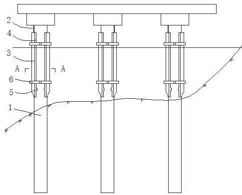
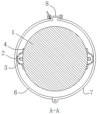
[0080] Specific embodiment 1: a monitoring method for high-pile wharf foundation piles, see Figure 1-2 In this method, the fiber strain sensor 2 is installed on the foundation pile 1, and one end of the optical fiber strain sensor 2 is connected to the control center (not shown in the figure) to realize the monitoring of the foundation pile. The optical fiber strain sensor 2 is installed vertically along the surface of the foundation pile 1 and is fixed and protected by the underwater epoxy resin covering the surface.

[0081] In this way, in this scheme, the optical fiber strain sensor is installed on the foundation pile and connected to the control center. The sensor can detect the stress change on the surface of the foundation pile in real time, and convert it into a detection signal to monitor the foundation pile. Among them, underwater epoxy resin is an existing curing material that can be used underwater. In the solution of the present invention, the optical fiber stra...

Embodiment 2

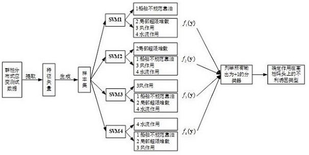
[0121] Example 2. The rest of this embodiment is the same as that of Embodiment 1, and the only difference is that the establishment, training and identification of the unfavorable inducement recognition classifier model are implemented in the following manner, see Figure 4 :

[0122] a. Identify adverse triggers and obtain test data;

[0123] First determine 6 kinds of unfavorable factors of high-piled wharf, 1=irregular berthing of ships, 2=uneven settlement of bank slope, 3=local overloading, 4=deterioration of material shape, 5=wind, wave and current impact, 6=earthquake Among them, the installed optical fiber strain sensor is used to obtain the distributed strain data of the pile group under the independent action of three unfavorable inducements: 1. ship irregular berthing, 3. local over-limit heap load and 5. wind, wave and current impact; at the same time, for the For the other three kinds of unfavorable causes, the ABAQUS numerical simulation model for high-piled w...


PUM


Abstract

The invention discloses a high-pile wharf foundation pile monitoring method based on unfavorable cause recognition, and the method comprises the steps: installing an optical fiber strain sensor on a foundation pile, and enabling one end of the optical fiber strain sensor to be connected with a control center, so as to achieve the monitoring of the foundation pile. The optical fiber strain sensor is provided with a part installed on the water of the foundation pile and a part installed under the water, and the optical fiber strain sensor is vertically arranged along the surface of the foundation pile in an attached mode and fixed and protected through underwater epoxy resin covering the surface. The method is convenient and fast to implement, the optical fiber sensor fixing and protecting effects are good, monitoring is more accurate and reliable, the service life is long, high pile damage inducing reasons can be analyzed, and wharf safety monitoring can be better achieved.

Description

[0001] This application is a divisional application of the patent "A Monitoring Method for High-Pile Wharf Foundation Pile" with the application number of 202110302961.8 and the application date of 2021-03-22. technical field [0002] The invention relates to the technical field of wharf safety monitoring, in particular to a high-piled wharf foundation pile monitoring method. Background technique [0003] High-piled wharf refers to a wharf mainly composed of superstructure, pile foundation and wharf equipment. The superstructure constitutes the wharf face and is integrated with the pile foundation, which directly bears the vertical and horizontal loads acting on the wharf face and transmits it to the pile foundation. The pile foundation is used to support the superstructure, and transfer the load of the superstructure and the wharf surface to the foundation through the interaction of piles and soil (rock). High-piled wharfs have the advantages of adapting to large water lev...

Claims


Application Information

Patent Timeline
Patent Type & Authority Applications(China)
IPC IPC(8): G01B11/16G01L1/24E02D33/00E02D5/22
CPCG01B11/18G01L1/242E02D33/00E02D5/22Y02E10/727
Inventor 周世良吴俊舒岳阶徐瑛孙世泉谢雷
Owner CHONGQING JIAOTONG UNIVERSITY
Learn More