
Traction transformer protection method, equipment and system

A traction transformer and equipment technology, applied in emergency protection circuit devices, electrical components, etc., can solve the problems of inconsistency between the actual transformer assembly parameters and the initial configuration, repeated equipment configuration, brake malfunction, etc., to reduce the number of chips and lines, The effect of high data transmission and calculation efficiency and improved accuracy

Active Publication Date: 2014-04-23
重庆新世纪电气有限公司
View PDF4 Cites 0 Cited by
  • Summary
  • Abstract
  • Description
  • Claims
  • Application Information

AI Technical Summary

Problems solved by technology

[0005] Due to the various forms of traction transformer windings, there is the problem of repeated equipment configuration in the form of multiple CPU protection measurement and control. Since the configuration of the substation according to the parameters before leaving the factory is not intuitive, it is easy to appear that the actual transformer assembly parameters do not match the initial configuration, and the differential protection adopts The split-phase braking protection is susceptible to maloperation due to factors such as load input; and because the traction transformer will generate a large excitation current when it is put into no-load or no-load into the transformer with distribution lines, it may cause braking misoperation

Method used


Image

  • Traction transformer protection method, equipment and system
  • Traction transformer protection method, equipment and system
  • Traction transformer protection method, equipment and system

Examples


Embodiment Construction

[0043] For reference and clarity, technical terms, abbreviations or abbreviations used hereinafter are summarized as follows:

[0044] LVDS: Low-Voltage Differential Signaling low voltage differential signal;

[0045] HMI: Human Machine Interface, man-machine interface;

[0046] M-LVDS: Multipoint low Voltage Differential Signaling, multipoint low voltage differential signal.

[0047] The following will clearly and completely describe the technical solutions in the embodiments of the present invention with reference to the accompanying drawings in the embodiments of the present invention. Obviously, the described embodiments are only some, not all, embodiments of the present invention. Based on the embodiments of the present invention, all other embodiments obtained by persons of ordinary skill in the art without creative efforts fall within the protection scope of the present invention.

[0048]In recent years, railway construction has gradually developed from electrificati...


PUM


Abstract

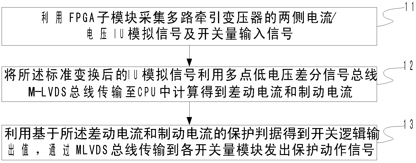
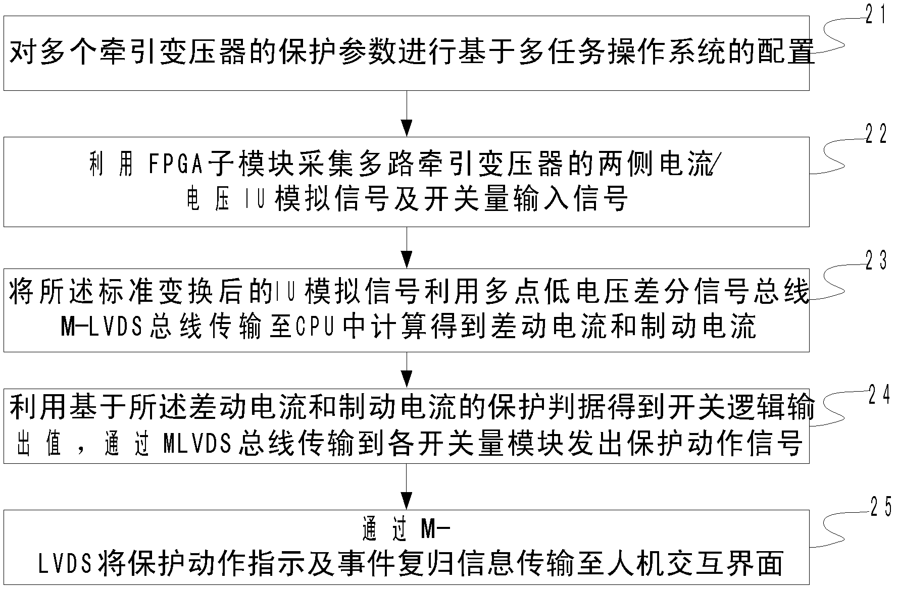
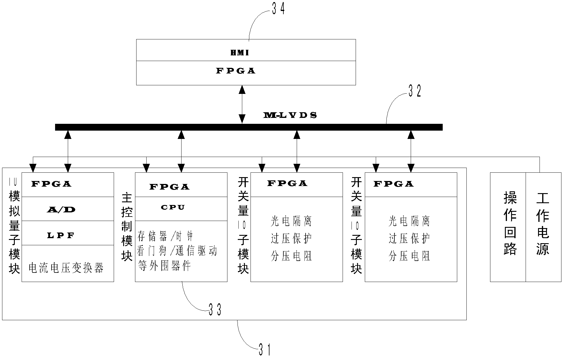
The embodiment of the invention discloses a traction transformer protection method, equipment and system. The method comprises the following steps of: acquiring the current / voltage IU analogue signals and switching value input signals on the two sides of a multi-channel traction transformer according to a preset frequency by use of FPGA (field programmable gate array) sub-modules controlled by an FPGA main module; transmitting the IU analogue signals after standard conversion to a CPU (central processing unit) through an M-LVDS (multipoint-low voltage differential signaling) bus to calculate the differential current and braking current, and obtaining a switching value logic output value by use of a protection criterion based on the differential current and braking current; and transmitting the switching value logic output value to an FPGA switching value input / output sub-module through the M-LVDS bus to send out a protection action signal. In the invention, different tasks are finished respectively in a centralized manner by combining the M-LVDS bus technology with multiple functional sub-modules of the FPGA, and the shortcoming of redundant hardware configuration caused by multi-CPU protection measurement and control is overcome.

Description

technical field [0001] The invention relates to the technical field of traction power supply protection for electrified railways, and more specifically relates to a traction transformer protection method, device and system. Background technique [0002] The traction substation is a substation that supplies power to the traction system. With the advancement of science and technology, railway construction is gradually developing from electrification to high-speed and dedicated passenger lines. As a key link in the railway power supply system, the performance of power supply and protection of the traction substation is directly related to the performance of the train. reliable operation of the power supply system. [0003] Traction transformers with different wiring modes and parameters are installed in each section according to actual application requirements. The existing traction substation needs to configure the coefficient matrix of differential current according to the pa...

Claims


Application Information

Patent Timeline
Patent Type & Authority Patents(China)
IPC IPC(8): H02H7/045
Inventor 张太勤孙小江
Owner 重庆新世纪电气有限公司
Learn More