Switched reluctance motor with dual-rotor structure
A technology of switched reluctance motor and double rotor, applied in the direction of magnetic circuit shape/style/structure, electrical components, electromechanical devices, etc., can solve the problem of low power density of switched reluctance motor, and achieve the effect of increasing power density
- Summary
- Abstract
- Description
- Claims
- Application Information
AI Technical Summary
Problems solved by technology
Method used
Image

Examples
Embodiment 1
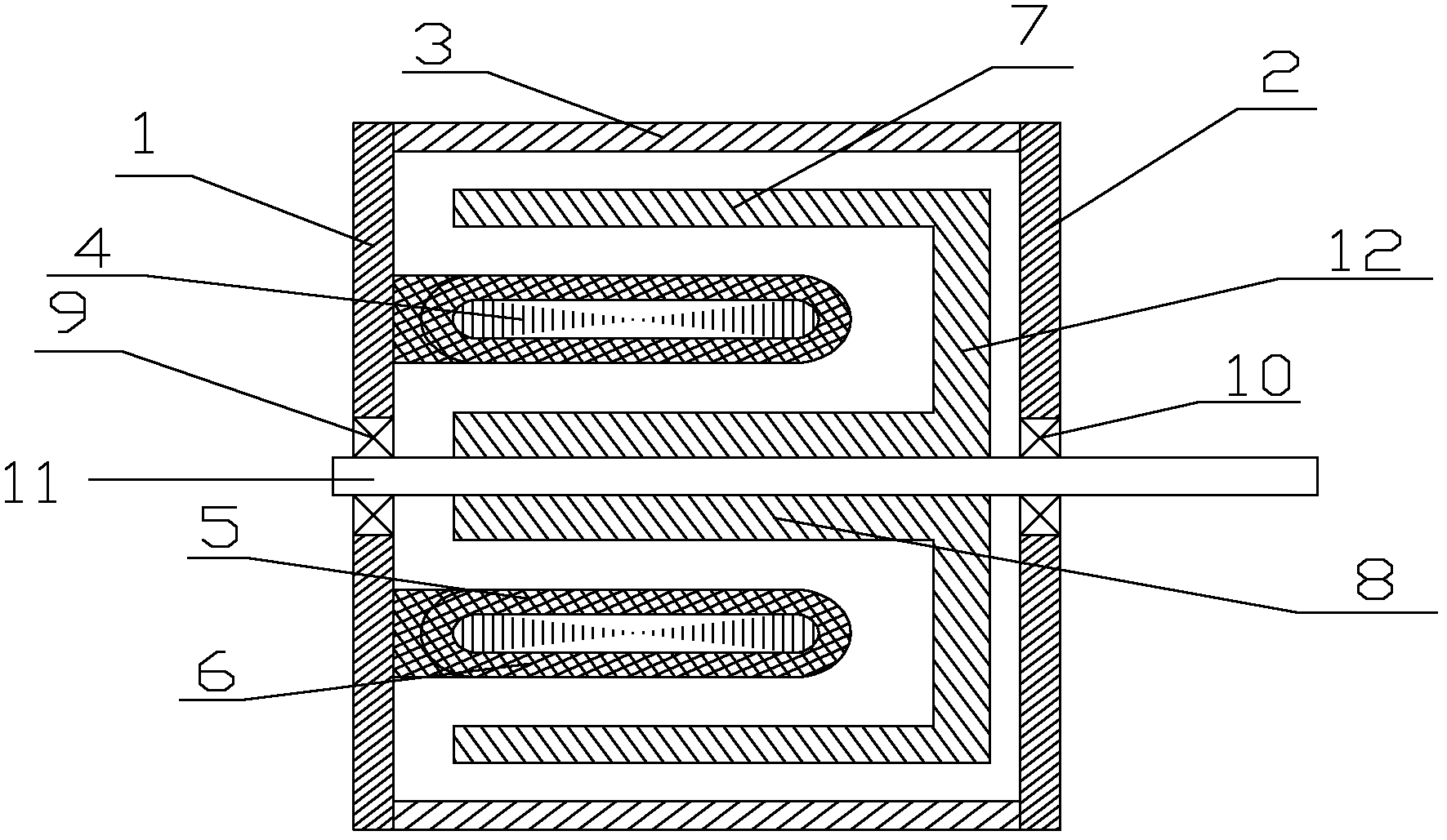
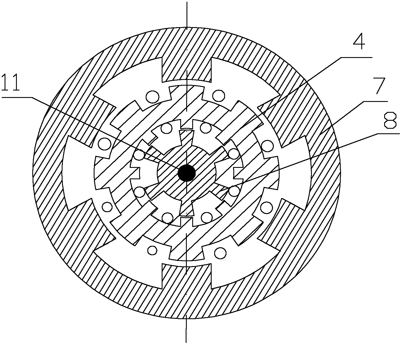
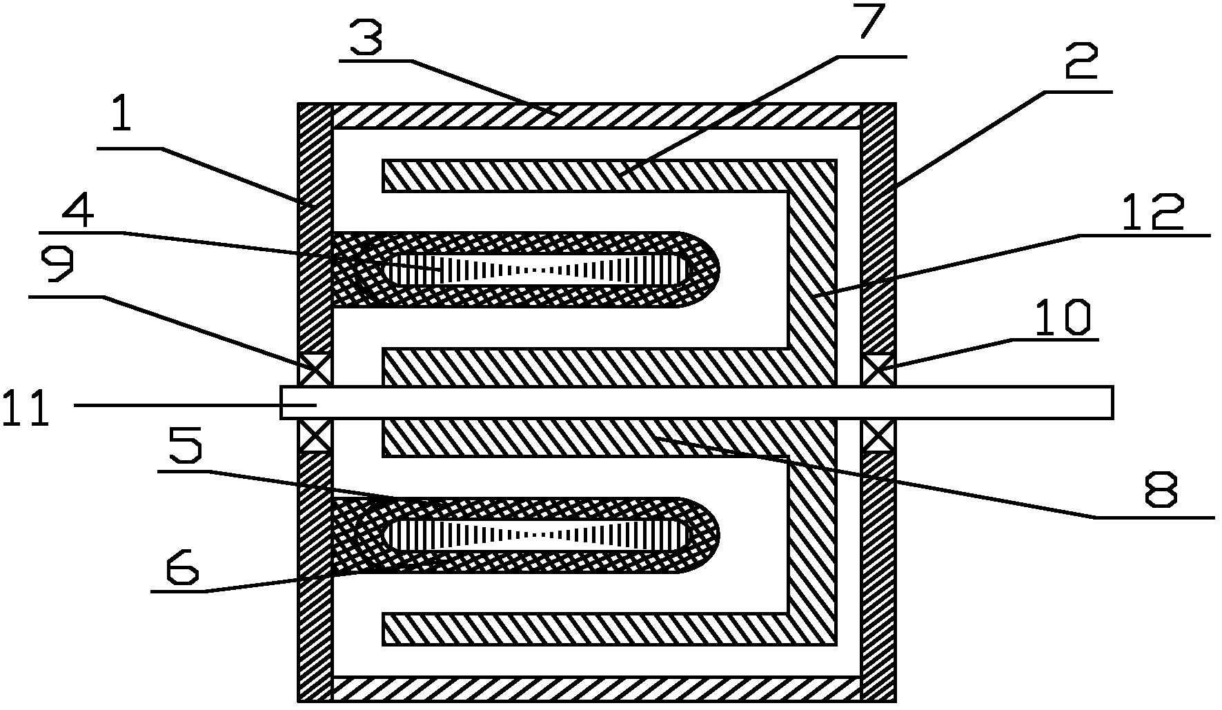
[0012] A dual rotor structure switched reluctance motor, such as figure 1 and figure 2 As shown, it includes left end cover 1, right end cover 2, casing 3, stator core 4, inner winding 5, outer winding 6, outer rotor core 7, inner rotor core 8, bearing A9, bearing B10, main shaft 11 and method Lan 12; the stator core 4, the inner winding 5 and the outer winding 6 form the stator part, which is fixedly connected to the left end cover 1; the left end cover 1 and the right end cover 2 are fixedly connected together through the casing 3; the outer rotor core One end of 7 and one end of inner rotor core 8 are fixedly connected into a whole through flange 12, and the whole is fixed on main shaft 11 through inner rotor iron core 8; main shaft 11 is rotationally connected with left end cover 1 through bearing A9, main shaft 11 passes Bearing B10 is rotationally connected with the right end cover 2; the inner and outer surfaces of the stator core 4 are salient pole structures, the nu...
PUM
 Abstract
Description
Claims
Application Information
 - Generate Ideas
- Intellectual Property
- Life Sciences
- Materials
- Tech Scout
- Unparalleled Data Quality
- Higher Quality Content
- 60% Fewer Hallucinations
Browse by: Latest US Patents, China's latest patents, Technical Efficacy Thesaurus, Application Domain, Technology Topic, Popular Technical Reports.
© 2025 PatSnap. All rights reserved.Legal|Privacy policy|Modern Slavery Act Transparency Statement|Sitemap|About US| Contact US: help@patsnap.com