Electric toothbrush and method of manufacturing an electric toothbrush

An electric toothbrush and its structure technology, which can be used in dentistry, brushes, brush bodies, etc., can solve problems such as inability to perceive, warning of excessive application pressure, etc.

Active Publication Date: 2014-12-03
BRAUN GMBH
View PDF10 Cites 0 Cited by
  • Summary
  • Abstract
  • Description
  • Claims
  • Application Information

AI Technical Summary

Problems solved by technology

Also, visually impaired persons are barely able to perceive these visually indicated warnings of excessive applied pressure

Method used


Image

  • Electric toothbrush and method of manufacturing an electric toothbrush
  • Electric toothbrush and method of manufacturing an electric toothbrush
  • Electric toothbrush and method of manufacturing an electric toothbrush

Examples


Embodiment Construction

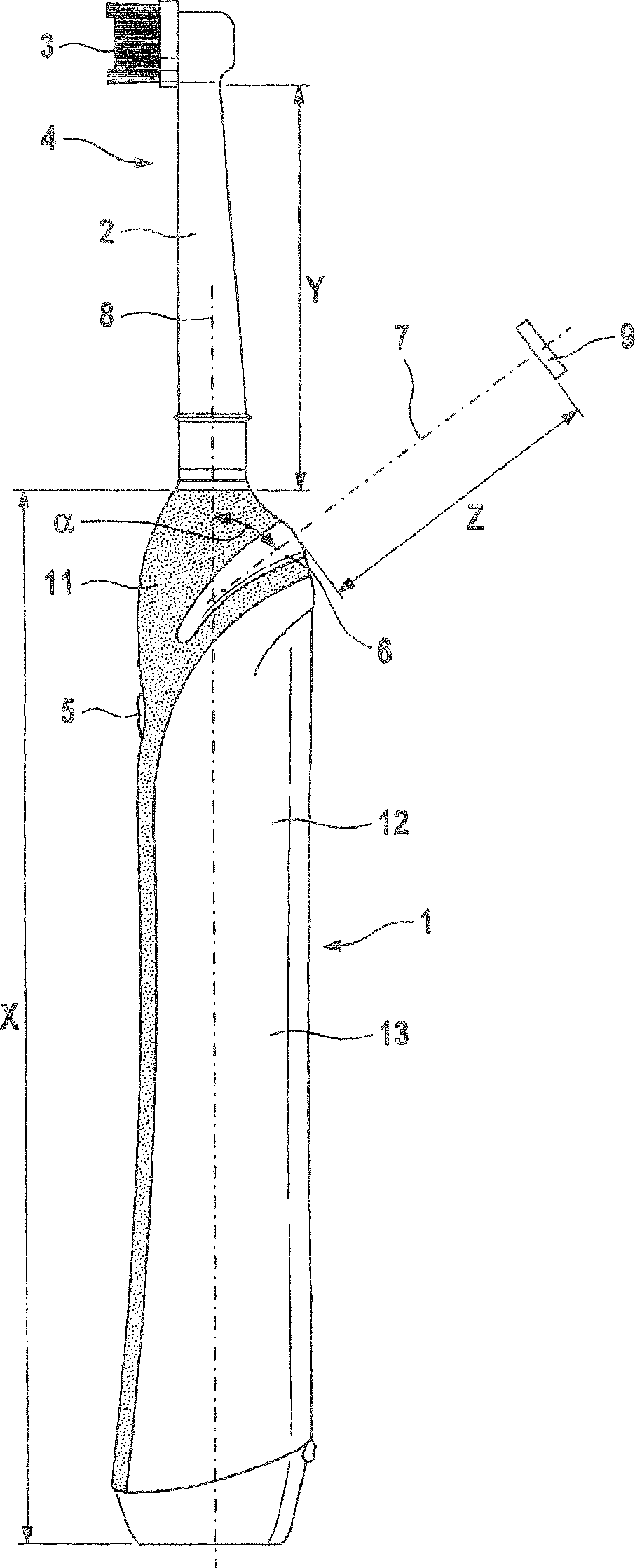
[0038] figure 1 An electric toothbrush is shown having a handpiece 1 extending from a lower end to an adjoining neck 2 (see figure 1 The length X) of the handpiece in . Plugged onto the handpiece 1 is an interchangeable replacement brush 4 having a neck 2 and a cleaning head 3 on its upper end. figure 1 Neck 2 in extends over length Y. The handpiece 1 also has a function switch 5 enabling the toothbrush to be switched on and off and (if applicable) switched to different operating modes. The function switch 5 is arranged on the same side of the electric toothbrush as the cleaning head 3 . Arranged on the side of the handpiece 1 opposite the function switch 5 and the cleaning head 3 is a light source 6 . The light source 6 is arranged in the upper region of the handpiece 1 directly adjacent to the replacement toothbrush 4 and above the function switch 5 . figure 1 Only the extension of the light source on the side shown facing away from the function switch is shown. Howeve...


PUM


Abstract

The toothbrush has a neck (2) arranged between a cleaning head (3) and a handpiece (1). The handpiece includes a housing (13) with an operating switch (5), an energy source, a drive unit, a control device and a light source (6) i.e. LED. The light source is activated by the control device when reaching a preset operating status. The light source is arranged in an upper region of the handpiece between the operating switch and the neck. The source emits light with light intensity of 50 to 2,500 micro watts per steradian and / or luminous intensity of 20 to 500 micro candela. An independent claim is also included for a method for manufacturing an electric toothbrush.

Description

technical field [0001] The present invention relates to electric toothbrushes and methods of making such toothbrushes. Electric toothbrushes often have a light source in the housing portion of the handpiece designed to indicate to the user a certain operating state of the toothbrush. For example, it is known to light up an LED on the housing to indicate the state of charge of the battery in the handpiece. Background technique [0002] WO92 / 13499 discloses an electric toothbrush with a light source in the upper region of the handpiece. The light source in this case is an LED, which is fixed directly in the housing of the electric toothbrush handpiece. [0003] US Patent 6,954,961 discloses an electric toothbrush of the type initially mentioned which uses LEDs for lighting around the handpiece. However, this concept is very difficult to implement in terms of its mechanical, electrical and optical implementation. In a variant of US patent 6,954,961 it is known to switch on ...

Claims


Application Information

Patent Timeline
Patent Type & Authority Patents(China)
IPC IPC(8): A61C17/22
CPCA61C17/221A61C17/225A46B15/0044A61C17/22A61C17/26A46B13/02
Inventor 奥利弗·格雷夫乌韦·滓特罗普利奥·法兰达克里斯蒂安·尤恩科彼得拉·安萨里
Owner BRAUN GMBH
Why Eureka
Try Eureka