A coupler secondary buffer device

A secondary buffer and coupler technology, applied in the field of vehicles, can solve the problems of shortening the service life of the coupler buffer device and increasing the coupler force, and achieves the effect of eliminating idle travel and prolonging the service life.

Active Publication Date: 2014-10-08
CRRC YANGTZE CO LTD
View PDF7 Cites 0 Cited by
  • Summary
  • Abstract
  • Description
  • Claims
  • Application Information

AI Technical Summary

Problems solved by technology

When the coupler changes from the traction working condition to the impact working condition, the gap between the buffer and the rear follower plate seat will cause the coupler to produce idle travel, resulting in a sudden increase in the coupler force, and in the long run, shortening the service life of the coupler buffer device

Method used


Image

  • A coupler secondary buffer device
  • A coupler secondary buffer device
  • A coupler secondary buffer device

Examples


Embodiment 1

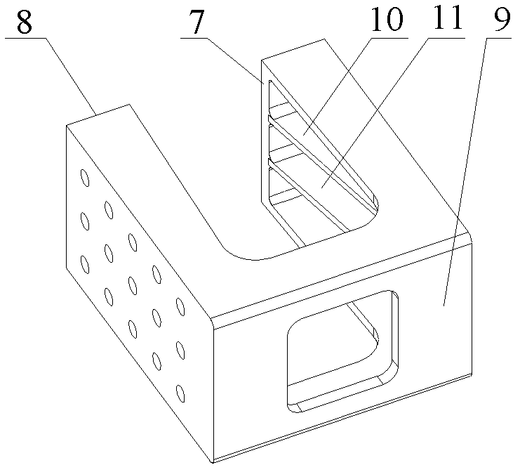
[0034] See attached figure 1 , in the coupler secondary buffer device provided by Embodiment 1 of the present invention, the rear slave plate seat includes the first baffle plate 7, the second baffle plate 8 and the third baffle plate 9, the first baffle plate 7, the second baffle plate 8 and the An inner chamber is formed between the third baffles 9 . In the cavity between the first baffle 7 and the third baffle 9 and in the cavity between the second baffle 8 and the third baffle 9, the first rib 10 and the second rib 11 are arranged respectively. , so that the inner cavity between the first baffle plate 7 and the third baffle plate 9 and the inner cavity between the second baffle plate 8 and the third baffle plate 9 are divided into three parts respectively. Wherein, in the inner cavity, the one between the first rib plate 10 and the second rib plate 11 is the middle cavity, and the one outside the first rib plate 10 and the second rib plate 11 are side cavities.

[0035] ...

Embodiment 2

[0040] See attached Figure 5 ~ attached Figure 7, as a preferred technical solution of Embodiment 1, a pair of second through holes are provided on the third baffle plate 9 at positions corresponding to the first through holes;

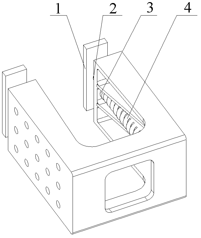
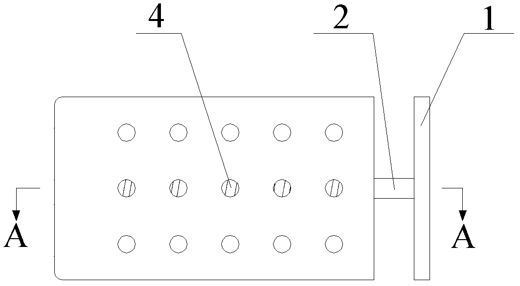
[0041] See attached Figure 7 , The second buffer section includes a push rod 2, a gasket 3, a guide rod 5, an elastic component and a locking component. In this embodiment, the elastic component is a spring 4, and the locking component is a nut 6. The buffer baffle 1 is fixedly connected to one end of the push rod 2, the push rod 2 passes through the first through hole, the other end of the push rod 2 is fixedly connected to one side of the gasket 3, and the other side of the gasket 3 is fixedly connected to the guide rod 5, the other end of the guide rod 5 protrudes from the second through hole, the protruding end of the guide rod 5 is locked by the nut 6, the spring 4 is sleeved on the guide rod 5, and one end of the spring 4 is against the was...

Embodiment 3

[0044] As a preferred technical solution of Embodiment 1, two pairs of first-type through holes symmetrical to each other are opened on the first baffle plate 7 and the second baffle plate 9 at positions corresponding to the side cavities, and the first buffer baffle plate The 1st and 2nd buffer baffles are respectively connected with the first type of buffer section through the first type of through holes.

[0045] When using the coupler secondary buffer device provided by Embodiment 3 of the present invention, in addition to the beneficial effects of the coupler secondary buffer device provided by Embodiment 1, since the first type of buffer joints increases from one pair to two pairs, the buffering effect Can be played better, and the size of the cushioning force that can be applied is greater.


PUM


Abstract

The invention discloses a secondary buffering device for a coupler, belonging to the technical field of vehicle. The secondary buffering device for a coupler is provided with at least one pair of first through holes symmetrical with each other on a baffle I and a baffle II of a rear draft lug and at the positions corresponding to cavities; the secondary buffering device for a coupler further comprises a buffering baffle I, a buffering baffle II and buffering joints having equal quantity with the first through holes, wherein the buffering baffle I and the buffering baffle II are connected with the buffering joints via the first through holes respectively. The secondary buffering device for a coupler is tightly attached to the rear seat of the original buffer box of vehicle and is not separated from the same during application process, thereby eliminating idle stroke existing when the coupler of railway wagon is converted to impact working condition from traction working condition; and proper buffering force is acted, thereby prolonging the service life of buffering device for coupler.

Description

technical field [0001] The invention relates to the technical field of vehicles, in particular to a coupler secondary buffer device provided with a secondary buffer device on an existing rear follower plate seat. Background technique [0002] In the prior art, when the rear follower seat is applied to the buffer device of the railway wagon coupler, there is a gap between the buffer and the rear follower seat. When the coupler changes from the traction working condition to the impact working condition, the gap between the buffer and the rear follower plate seat will cause the coupler to produce idle travel, resulting in a sudden increase in the coupler force. If things go on like this, the service life of the coupler buffer device will be shortened. Contents of the invention [0003] In order to solve the above-mentioned problems, the present invention proposes a coupler secondary buffer device provided with a secondary buffer device on the existing rear follower plate. ...

Claims


Application Information

Patent Timeline
Patent Type & Authority Patents(China)
IPC IPC(8): B61G9/04
Inventor 李晓军林量才
Owner CRRC YANGTZE CO LTD
Why Eureka
Try Eureka