Supercharge Your Innovation With Domain-Expert AI Agents!

Material stirring device

A mixing device and material technology, applied in roads, road repairs, roads, etc., can solve the problem that materials cannot be fully mixed

Active Publication Date: 2012-06-20
ZOOMLION HEAVY IND CO LTD
View PDF7 Cites 7 Cited by
  • Summary
  • Abstract
  • Description
  • Claims
  • Application Information

AI Technical Summary

Problems solved by technology

[0007] An object of the present invention is to provide a material stirring device to solve

Method used


Image

  • Material stirring device
  • Material stirring device
  • Material stirring device

Examples


Embodiment Construction

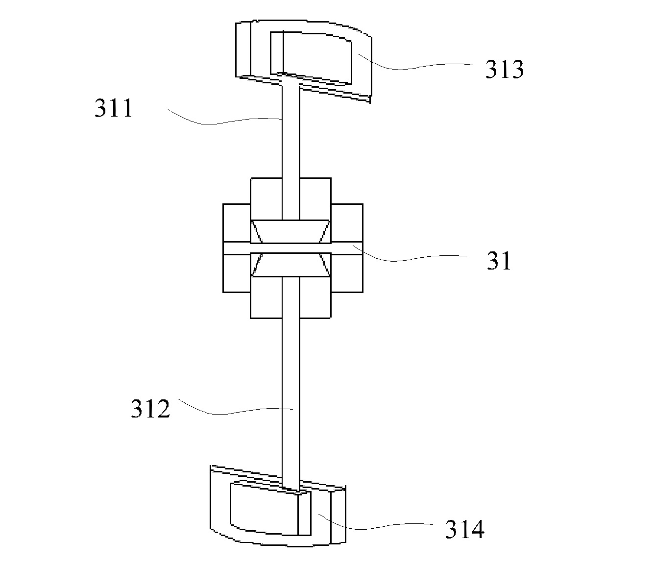
[0044] In order to fully stir the materials in the vicinity of the stirring shaft, the present invention provides a material stirring device, which includes a stirring shaft 31 and multiple groups of stirring units installed on the stirring shaft in sequence along the axial direction. Stirring unit structure such as image 3 As shown, each stirring unit includes at least one stirring arm 311 on the stirring shaft, the stirring arm is provided with stirring blades, and the distance between at least two stirring blades 313, 314 and the stirring shaft 31 is different. In this material stirring device, because there are at least two stirring blades 313 and 314 and the distance between the stirring shaft is different, therefore, the different stirring blades with the distance between the stirring shaft can make the center of the stirring shaft in the material stirring device Materials in both near and far areas can be thoroughly mixed. The material mixing device can be used in mix...


PUM


Abstract

Aiming at solving the problem that the materials at the nearby area surrounding a stirring shaft in a conventional material stirring device can not be stirred sufficiently, the invention provides a material stirring device which comprises a stirring shaft and a plurality of groups of stirring units sequentially installed on the stirring shaft along the axial direction. Each stirring unit comprises at least one stirring arm and at least two stirring blades arranged on the stirring arm. The stirring arm is fixed on the stirring shaft, and the distances between at least two stirring blades and the stirring shaft are different. In this way, when the stirring shaft rotates around the axis, the materials in the surrounding area near to or far from the stirring shaft can all be stirred. Therefore, the materials can be stirred sufficiently.

Description

technical field [0001] The invention relates to the technical field of engineering machinery, in particular to a material stirring device. Background technique [0002] Asphalt mixing equipment (also known as asphalt mixing equipment or asphalt mixing plant) is the key equipment for asphalt pavement construction. It is mainly used to mix sand and gravel, asphalt, mineral powder and other materials into asphalt mixture. The performance of the asphalt mixing plant itself is related to the uniformity of the asphalt mixture and the efficiency of the asphalt mixing plant. [0003] Existing asphalt mixing equipment can refer to the patent that the Chinese patent application number is 2000920034640.9. Such as figure 1 As shown, the existing stirring equipment adopts an opposed stirring device. Opposed stirring units are sequentially installed on the stirring shaft, and the stirring shaft 13 and the opposed stirring unit mounted on it form an opposed structure that continuously p...

Claims


Application Information

Patent Timeline
IPC IPC(8): E01C19/10
Inventor 尹友中
Owner ZOOMLION HEAVY IND CO LTD
Features
  • R&D
  • Intellectual Property
  • Life Sciences
  • Materials
  • Tech Scout
  • Unparalleled Data Quality
  • Higher Quality Content
  • 60% Fewer Hallucinations
Learn More