Time-of-flight depth imaging

A depth image and depth technology, applied in image analysis, image communication, image data processing, etc., can solve problems such as inaccuracy, depth camera damage, and depth measurement

Active Publication Date: 2012-06-27
MICROSOFT TECH LICENSING LLC
View PDF7 Cites 17 Cited by
  • Summary
  • Abstract
  • Description
  • Claims
  • Application Information

AI Technical Summary

Problems solved by technology

However, the aforementioned differences in the two depth measurements can make it difficult to correlate the dep

Method used


Image

  • Time-of-flight depth imaging
  • Time-of-flight depth imaging
  • Time-of-flight depth imaging

Examples


Embodiment Construction

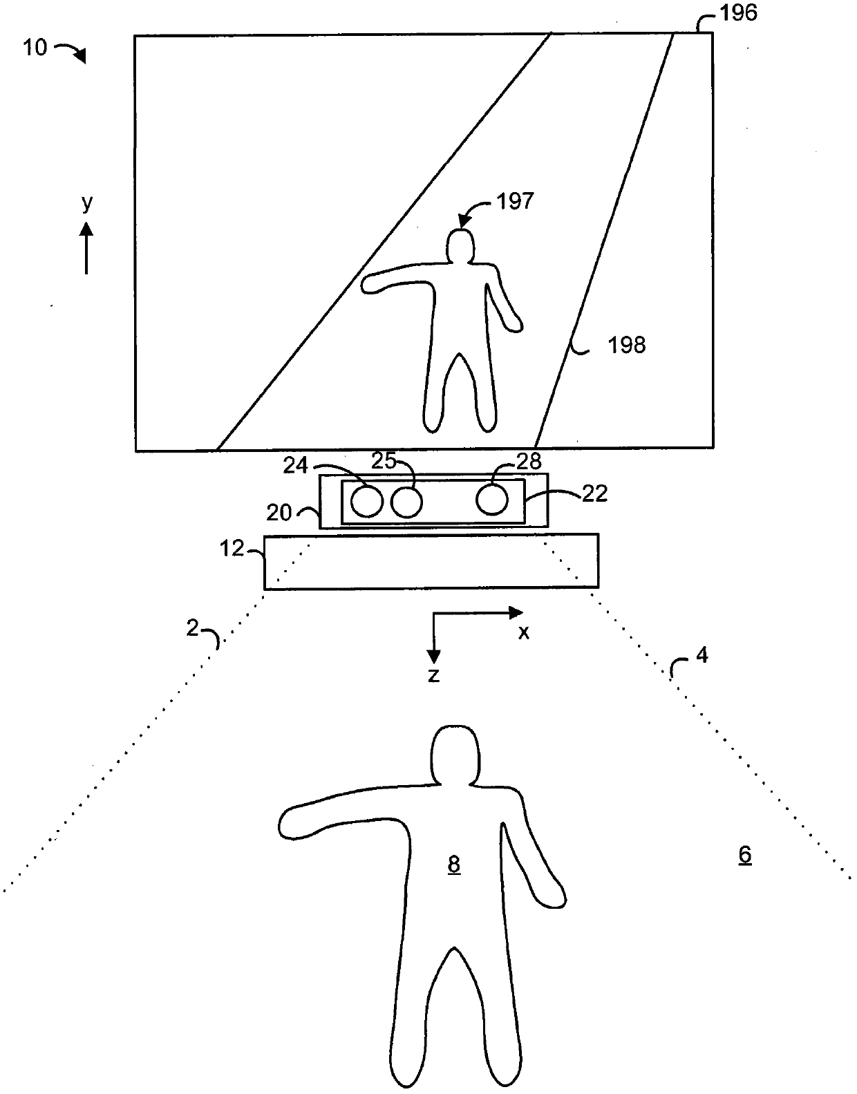
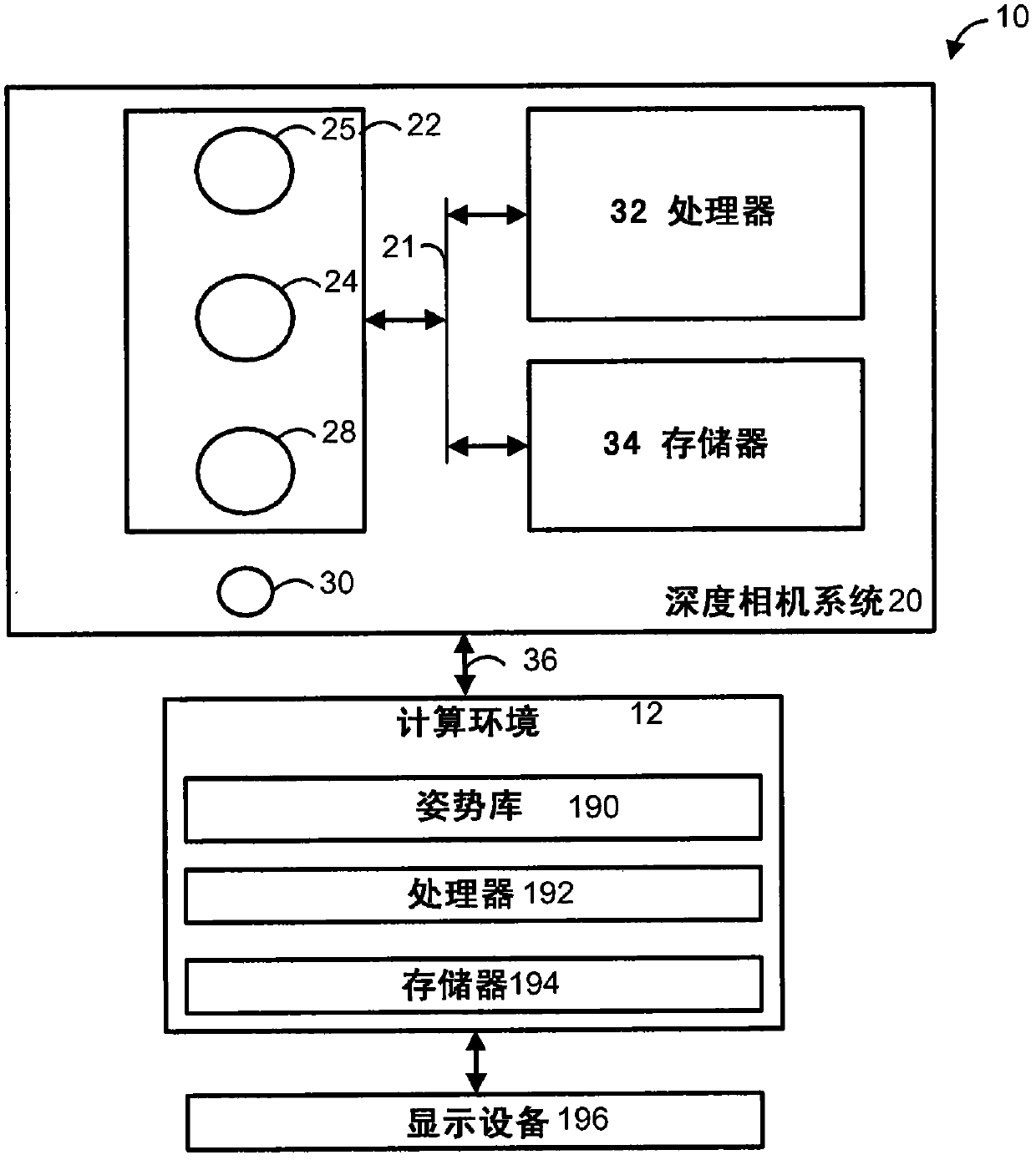
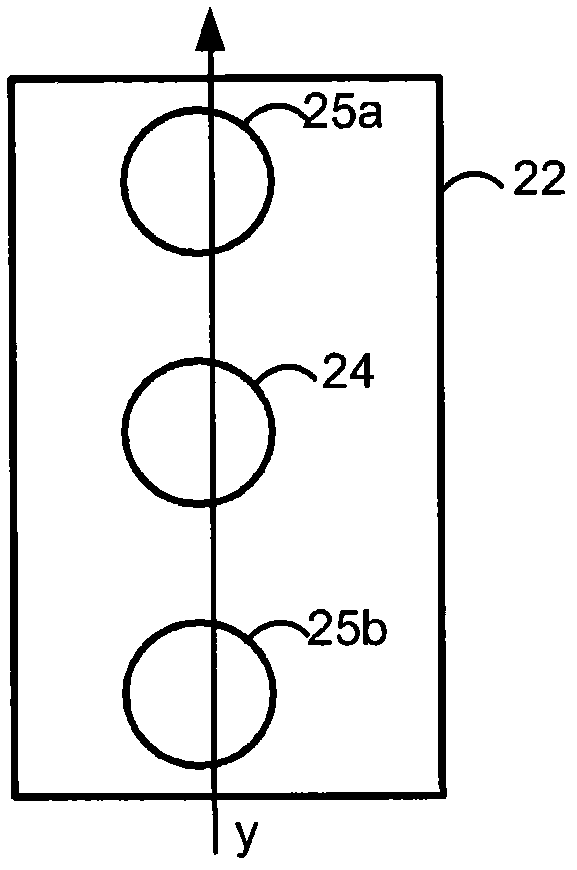
[0028] Techniques for determining depth to an object are provided. A depth image is determined based on two light intensity images collected at different locations or times. For example, a light beam is emitted into a field of view where two image sensors at slightly different positions are used to collect two input light intensity images. Alternatively, light intensity images may be collected from the same sensor but at different times. A depth image can be generated based on these two light intensity images. This technique compensates for differences in the reflectivity of objects in the field of view. However, there may be some misalignment between pixels in these two light intensity images. An iterative process can be used to alleviate the need for exact matching between light intensity images. This iterative process may involve modifying one of the light intensity images based on a smoothed version of the depth image generated from the two light intensity images. Sub...


PUM


Abstract

Techniques are provided for determining depth to objects. A depth image may be determined based on two light intensity images. This technique may compensate for differences in reflectivity of objects in the field of view. However, there may be some misalignment between pixels in the two light intensity images. An iterative process may be used to relax a requirement for an exact match between the light intensity images. The iterative process may involve modifying one of the light intensity images based on a smoothed version of a depth image that is generated from the two light intensity images. Then, new values may be determined for the depth image based on the modified image and the other light intensity image. Thus, pixel misalignment between the two light intensity images may be compensated.

Description

technical field [0001] The present invention relates to depth imaging, and more particularly to time-of-flight depth imaging. Background technique [0002] Depth camera systems obtain data about the position of a person or other object within physical space. The camera has one or more sensors with pixels that collect light intensity. Depth values ​​can be determined from light intensity. For example, light intensity data from two sensors can be correlated and a depth value for each pixel can be determined. Depth values ​​may be input to applications within the computing system for a variety of applications. There can be many applications such as for military, entertainment, sports and medical purposes. For example, depth values ​​for a person can be mapped to a three-dimensional (3-D) human skeletal model and used to create an animated character or avatar. [0003] To determine depth values, a depth camera may project light onto objects in the camera's field of view. L...

Claims


Application Information

Patent Timeline
IPC IPC(8): G03B35/08G03B15/05H04N5/232G01S17/18G01S17/32G01S17/894
CPCG01S17/50G06T7/0075G01S17/89G06T7/0065G01S17/32G01S17/107G06T7/593G01S17/18G01S17/894
Inventor S·卡茨A·阿德莱尔
Owner MICROSOFT TECH LICENSING LLC
Why Eureka
Try Eureka