Vehicular audio encoder

A car audio and encoder technology, applied in the encoder field, can solve problems such as driving bumps, large frictional resistance, and torque drop, and achieve smooth and stable torque changes, prolong service life, and relieve excessive pressure.

Active Publication Date: 2015-03-04
HUIZHOU TRANTEK ELECTRONICS
View PDF6 Cites 0 Cited by
  • Summary
  • Abstract
  • Description
  • Claims
  • Application Information

AI Technical Summary

Problems solved by technology

The use environment of car audio and other products is complex, and the vehicle is prone to bumps when driving in bad road conditions. Due to the light torque of the traditional encoder product, the car audio control button is prone to autorotation during the bumpy process of the vehicle, thereby automatically changing the car audio. The playback status of
In response to this situation, a high torque encoder is produced, such as figure 1 As shown, the encoder includes a cover (1), a rotating shaft (2), a shaft sleeve (3), a snap ring (4), a spring washer (5), a rotor (6), silica gel particles (7), shrapnel (8 ), the needle seat (9), and the bottom plate (10). After assembly, the encoder realizes product function switching through the rotation of the shaft (2). When the shaft rotates, it drives the rotor to rotate together, while the spring washer (5) does not move. When designing The frictional resistance generated by the interference fit of the spring washer (5) to the rotor (6) forms a torsion force. The greater the torsion force, the greater the frictional resistance, and the greater the wear and tear, the shorter the life of the product, and vice versa. Long, can't have both
Due to the above reasons, the lifespan of this kind of encoder cannot meet the requirements of the car audio, and the torque is likely to decrease after long-term use, so it cannot completely solve the problem of easy loosening when used in a vibrating environment

Method used


Image

  • Vehicular audio encoder
  • Vehicular audio encoder
  • Vehicular audio encoder

Examples


Embodiment Construction

[0012] In order to facilitate the understanding of those skilled in the art, the present invention will be further described in detail below with reference to the drawings and embodiments.

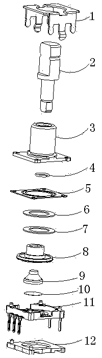
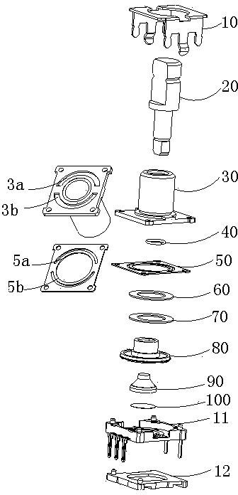
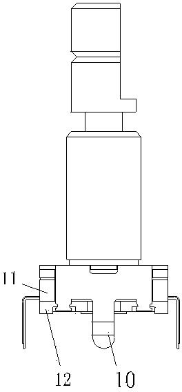
[0013] Such as Figure 2~4 As shown, the car audio encoder disclosed by the present invention includes a base and an upper cover 10, and a rotary encoding assembly and a pressing assembly installed in the base. The base includes a needle base 11 and a bottom plate 12 installed below the needle base. The base 11 has an inner cavity, and the rotary encoding component and the pressing component are installed in the inner cavity of the needle base 11 .

[0014] Wherein, the rotary encoding assembly includes a rotating shaft 20 , a shaft sleeve 30 , a snap ring 40 , a spring washer 50 , an elastic buffer plate 60 , a friction plate 70 , and a rotor 80 . The spring washer 50 is installed on the base, and the shaft sleeve is also installed on the base, and the lower end presses the spring washer...


PUM


Abstract

The invention relates to a vehicular audio encoder, which comprises a base, an upper cover and a rotary encoding component mounted in the base. The rotary encoding component comprises a rotary shaft, a shaft sleeve, a spring washer, an elastic buffer plate, a friction plate and a rotor. The rotary shaft is sleeved into the shaft sleeve, the lower end of the rotary shaft penetrates through the spring washer, the elastic buffer plate and the friction plate to extend into the rotor to drive the rotor to rotate, and the upper end of the rotary shaft is exposed out of the upper cover for operation. The rotor rotates to be in direct friction with the spring washer, and the friction plate and the spring washer are in interference fit to generate extrusion so as to deform the buffer plate and pressurize the friction plate and the plastic rotor to generate high torsion. The spring washer is provided with a buffer protrusion, and the shaft sleeve is provided with a clearance groove at a corresponding position. The buffer plate and the friction plate are additionally arranged between the rotor and the spring washer, the utilization requirement of long service life of products can be met while high torsion of the products is guaranteed by means of deformation of the spring plate and the buffer plate and mutual cooperation of the friction plate and the rotor.

Description

technical field [0001] The invention relates to an encoder, in particular to an encoder used on a car audio system. Background technique [0002] Encoders are required for car audio. The use environment of car audio and other products is complex, and the vehicle is prone to bumps when driving in bad road conditions. Due to the light torque of the traditional encoder product, the car audio control button is prone to autorotation during the bumpy process of the vehicle, thereby automatically changing the car audio. playback status. In response to this situation, a high torque encoder is produced, such as figure 1 As shown, the encoder includes a cover (1), a rotating shaft (2), a shaft sleeve (3), a snap ring (4), a spring washer (5), a rotor (6), silica gel particles (7), shrapnel (8 ), the needle seat (9), and the bottom plate (10). After assembly, the encoder realizes product function switching through the rotation of the shaft (2). When the shaft rotates, it drives the ...

Claims


Application Information

Patent Timeline
Patent Type & Authority Patents(China)
IPC IPC(8): H01H19/02H01H19/54
Inventor 郑万峰陈红吴功伟
Owner HUIZHOU TRANTEK ELECTRONICS
Why Eureka
Try Eureka