Heat exchange system and heat exchange method

A technology of heat exchange system and heat exchange module, which is applied in the field of battery heat exchange, can solve the problems of low energy utilization rate and high energy consumption of power supply system, and achieve the effect of ensuring good operation and solving high energy consumption

Active Publication Date: 2012-06-27
DONGFANG ELECTRIC (CHENGDU) HYDROGEN FUEL CELL TECH CO LTD
View PDF3 Cites 2 Cited by
  • Summary
  • Abstract
  • Description
  • Claims
  • Application Information

AI Technical Summary

Problems solved by technology

[0007] The present invention aims to provide a heat exchange system and heat exchange method to solve the problems of high energy consumption and low energy utilization rate of power supply systems in the prior art

Method used


Image

  • Heat exchange system and heat exchange method
  • Heat exchange system and heat exchange method
  • Heat exchange system and heat exchange method

Examples


Embodiment Construction

[0032] It should be noted that, in the case of no conflict, the embodiments in the present application and the features in the embodiments can be combined with each other. The present invention will be described in detail below with reference to the accompanying drawings and examples.

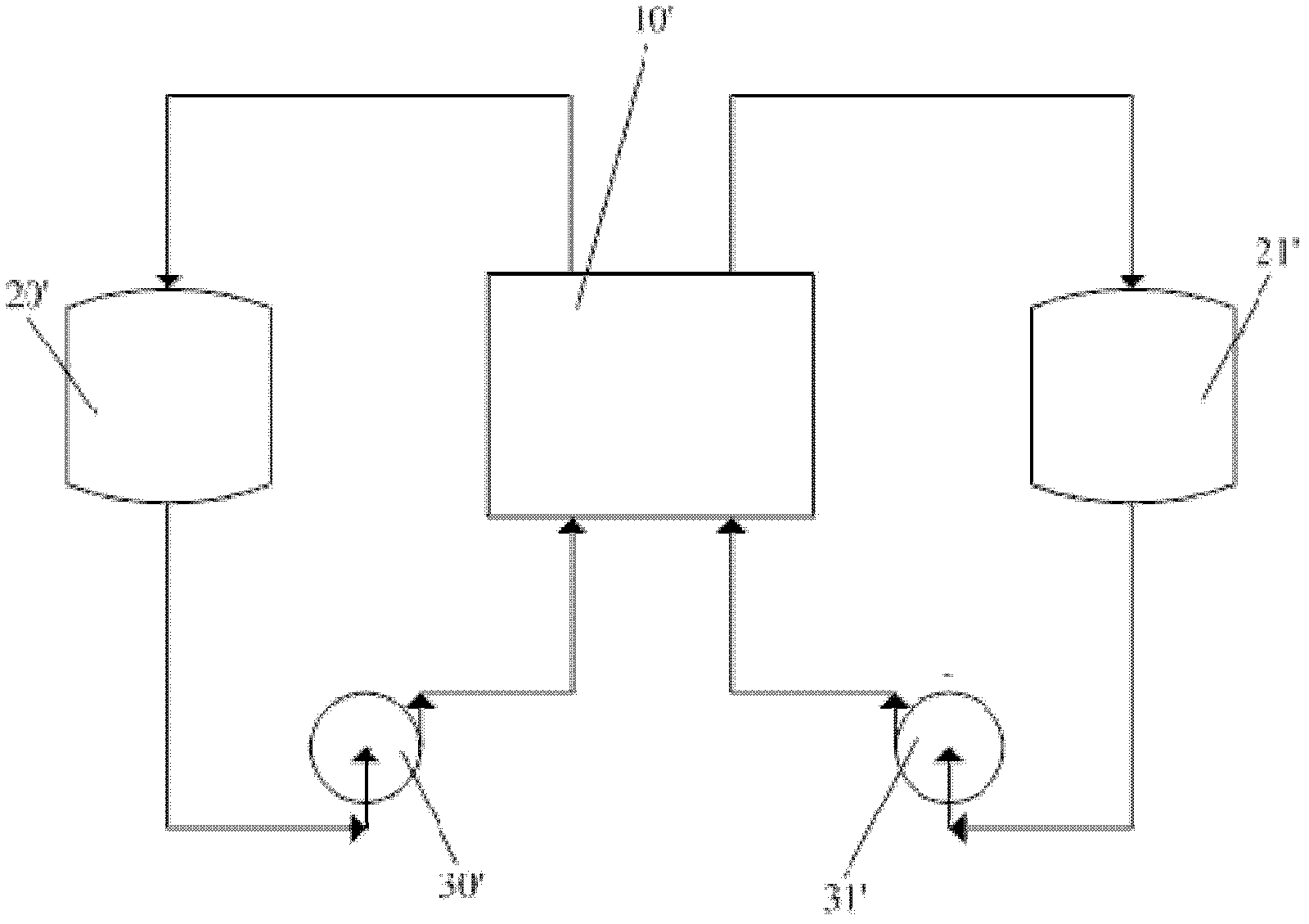
[0033] The heat exchange system provided by the present invention includes a power supply sub-system and a heat exchange sub-system, and the battery modules of the power supply sub-system include a vanadium battery module, a fuel cell module and other power supply modules (such as solar energy, sodium-sulfur battery) and the like. In order to clearly describe the embodiment of the present invention, the flow battery system and the fuel cell system in the prior art are firstly introduced. figure 1 A schematic diagram showing a flow battery system in the prior art, such as figure 1 As shown, the liquid flow battery system includes a battery stack 10', a positive electrode electrolyte liquid stor...


PUM


Abstract

The invention provides a heat exchange system and a heat exchange method. The heat exchange system comprises a power supply subsystem and a heat exchange subsystem, the power supply subsystem comprises a battery module and is used for delivering electric energy for a terminal user, the heat exchange subsystem comprises a heat exchange module and is used for dissipating heat of the power supply subsystem, and simultaneously, recycled heat energy is used for being delivered to the terminal user. Heat energy generated by the power supply subsystem during working is managed and optimized in a unified manner, the efficiency of the system is effectively increased, the service life of the system is prolonged, and the integration level of the system is improved. Simultaneously, problems that in the prior art, energy consumption of a power supply system is high, and energy utilization rate is low is effectively are effectively resolved.

Description

technical field [0001] The invention relates to the technical field of battery heat exchange, in particular to a heat exchange system and a heat exchange method. Background technique [0002] A fuel cell is an environmentally friendly, efficient, and long-life power generation device. Taking the proton exchange membrane fuel cell (PEMFC) as an example, the fuel gas enters from the anode side, the hydrogen atoms lose electrons at the anode and become protons, the protons pass through the proton exchange membrane to the cathode, and the electrons also reach the cathode through the external circuit, at the cathode protons , electrons and oxygen combine to form water. The fuel cell converts chemical energy into electrical energy in a non-combustion manner, and its direct power generation efficiency can be as high as 45% because it is not limited by the Carnot cycle. With the battery stack as the core power generation device, the fuel cell system integrates power management, th...

Claims


Application Information

Patent Timeline
Patent Type & Authority Applications(China)
IPC IPC(8): H01M8/04H01M8/02H01M8/04007
CPCY02E60/50
Inventor 汤浩王晶杨海玉张晓晶张占奎殷聪
Owner DONGFANG ELECTRIC (CHENGDU) HYDROGEN FUEL CELL TECH CO LTD
Why Eureka
Try Eureka