Bottom filter structure of three-layer filter

A filtration structure and filter technology, applied in fixed filter element filters, filtration separation, chemical instruments and methods, etc., can solve the problems of troublesome removal and cleaning, increase the time of filtration process, gas short circuit, etc., and achieve convenient removal. filter cake effect

Inactive Publication Date: 2012-07-04
苏州恒尔机械制造有限公司
View PDF1 Cites 0 Cited by
  • Summary
  • Abstract
  • Description
  • Claims
  • Application Information

AI Technical Summary

Problems solved by technology

[0003] However, although its embodiment 1 and 2 can realize the convenience of unloading slag, but for the solid capacity lower than the uppermost filter tube plane, gas short circuit phenomenon will occur during gas pressure filtration, and there will still be residual liquid
If reduce its filtration installation layer number, although can reduce remaining liquid, must lose filtration area, increase filtration process time exponentially; Its embodiment 3 realizes layering by arc-shaped filtrate collection branch pipe, although can realize that there is no remaining liquid after filtering or The remaining liquid is minimized, but because the arc-shaped filtrate collection branch pipe used to collect the filtrate is set above the installation partition, the filter cake is instead combined in the frame formed by the arc-shaped filtrate collection branch pipe and the filter tube after the bottom cover is opened, making Unloading and cleaning is quite troublesome, and there are dead corners that are difficult to clean and unload the filter cake

Method used


Image

  • Bottom filter structure of three-layer filter
  • Bottom filter structure of three-layer filter
  • Bottom filter structure of three-layer filter

Examples


Embodiment Construction

[0022] In order to make the object, technical solution and advantages of the present invention clearer, the present invention will be further described in detail below in conjunction with the accompanying drawings and embodiments. It should be understood that the specific embodiments described here are only used to explain the present invention, not to limit the present invention.

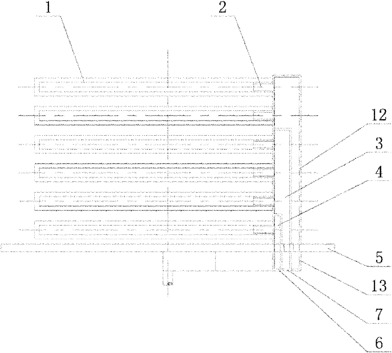
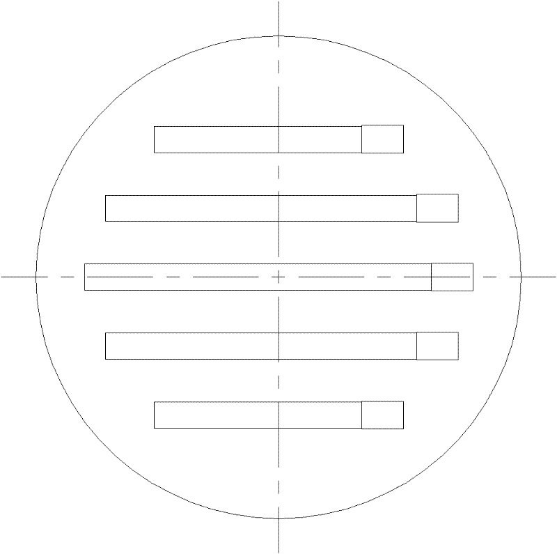
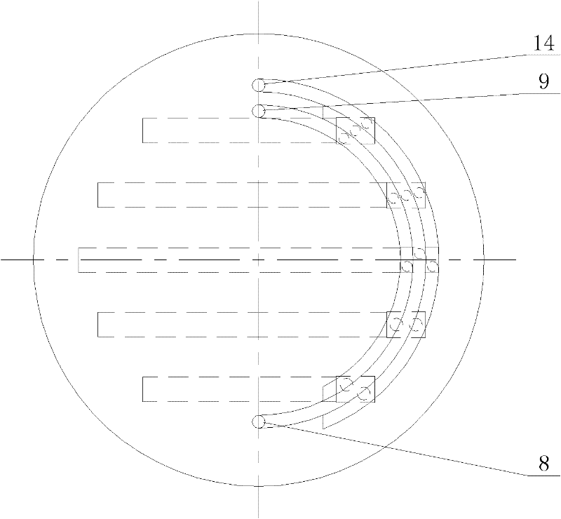
[0023] Such as figure 1 As shown, the present invention provides a bottom filtration structure of a three-layer filter, which includes a filter pipe 1, an installation partition 5, the first, second and third sets of vertical collection chambers 3, 4 and 12, and the first , the second and the third arc-shaped sump tanks 6, 7 and 13, wherein the filter tube is a multi-layer structure arranged horizontally, and the first, second and third groups of vertical sump chambers 3, 4 and 12 are respectively connected to Different layers of filter tubes 1; first, second and third groups of drainage holes (no...


PUM


Abstract

The invention discloses a bottom filter structure of a three-layer filter. The bottom filter structure is characterized by comprising filter tubes, an installation spacer plate, first, second and third groups of upright liquid converging cavities, and first, second and third arc-shaped liquid converging tanks, wherein the filter tubes are of a horizontally arranged multilayer structure, the first, second and third groups of upright liquid converging cavities are respectively connected with the filter tubes in different layers; first, second and third groups of drainage holes are formed on the installation spacer plate, the first, second and third groups of upright liquid converging cavities are respectively corresponding to the first, second and third groups of drainage holes and installed above the installation spacer plate; the first, second and third arc-shaped liquid converging tanks are respectively corresponding to the first, second and third groups of upright liquid converging cavities and installed below the installation spacer plate; and the first, second and third arc-shaped liquid converging tanks are also respectively connected with first, second and third liquid outlet connecting tubes. The bottom filter structure of the three-layer filter is convenient to unload the filter cake and achieves the aim of leaving no residual liquid after filtering as much as possible.

Description

technical field [0001] The invention relates to a filtering device, in particular to a bottom filtering structure of a three-layer filter. Background technique [0002] The State Intellectual Property Office announced on January 19, 2005, the patent number ZL200420004020.8 is a utility model patent named "bottom filter mechanism of vertical filter", which discloses a filter structure at the bottom of a vertical filter , it changes the traditional mechanism from the original filter tube perpendicular to the filter structure at the bottom of the horizontal mounting plate to the horizontal setting, according to its embodiment, it can solve the function of facilitating slag unloading or realizing no residual liquid to a certain extent. [0003] However, although its embodiment 1 and 2 can realize slag unloading convenience, for the solid capacity lower than the uppermost filter tube plane, gas short circuit phenomenon will occur during gas pressure filtration, and there will sti...

Claims


Application Information

Patent Timeline
Patent Type & Authority Applications(China)
IPC IPC(8): B01D29/33B01D29/54B01D35/16
Inventor 章建朋
Owner 苏州恒尔机械制造有限公司
Why Eureka
Try Eureka