Ultra cleaning of combustion gas including the removal of CO.sub.2

a technology of combustion gas and cleaning equipment, which is applied in the direction of emission prevention, separation processes, lighting and heating apparatus, etc., can solve the problems of high cost of capturing the last few percents of harmful contaminants, and the inability to operate with dirty, etc., to achieve the effect of reducing the moisture content, low volume and high co2 concentration

Active Publication Date: 2010-01-05
GENERAL ELECTRIC TECH GMBH
View PDF85 Cites 60 Cited by
  • Summary
  • Abstract
  • Description
  • Claims
  • Application Information

AI Technical Summary

Benefits of technology

[0020]The present invention is an integrated method and system to efficiently and cost effectively reduce the emission of residuals, such as SO2, SO3, HCl, HF and particulate matter including PM2.5, from combustion gas, downstream of conventional air pollution control systems, to near zero levels. Further, the system of the current invention reduces CO2 emission by capturing and delivering it to sequestration in a concentrated form and at high pressure. It is the objective of this invention that the process would be relatively uncomplicated, would utilize low cost reagent, would generate no additional waste streams and most importantly, would be a low cost and low energy consumer.
[0021]The present invention is a wet method and system whereby the saturated combustion gas, downstream of conventional air pollution control equipment and system, is cooled to well below its ambient saturation temperature. The cooling is achieved by direct contact with cold water in dedicated vessels. The direct contact between the gas and the liquid, combining with massive condensation of moisture from the saturated gas, is a very efficient wet scrubber. Optionally, alkaline materials such as sodium or ammonium carbonate can be added to the direct contact cooler to enhance the capture of the acidic species in the gas. The direct cooling to low temperature can be achieved in one or more cooling stages. Continuous bleed from the direct contact cooler, prevents the accumulation of the captured contaminants in the direct contact coolers.
[0023]In accordance with the current invention, cooling of the gas substantially reduces its moisture content. The cooled and low moisture gas has relatively low volume and relatively high CO2 concentration thus making the efficient capture of CO2 easier and lower cost.
[0024]The invention further involves the mass transfer and the reaction of gaseous CO2 from the combustion gas with CO2-lean ammoniated solution to form CO2-rich ammoniated solution. According to the current invention, the absorption reaction occurs in a CO2 absorber operating at about atmospheric pressure and at low temperature preferably in the temperature range of 0-20, or even 0-10, degrees Celsius. The low temperature enhances mass transfer of CO2 to the solution while substantially reducing the vapor pressure of ammonia and preventing its evaporation into the gas stream. One or more stages of CO2 absorption can be used depending on the capture efficiency requirements.
[0026]The regeneration reaction is endothermic. However, the heat of reaction is low and the overall heat consumption of the process is relatively low. Moreover, the high-pressure regeneration minimizes the evaporation of ammonia and water thus minimizing the energy consumed in the process. Also, low-grade heat can be used for the regeneration of the CO2 to further reduce the impact of the CO2 capture on the overall efficiency of the plant. The CO2-lean solution used in the absorber to capture the CO2 contains NH3 / CO2 mole ratio in the range of 1.5-4.0 and preferably in the range of 1.5-3.0. The CO2-rich solution sent for regeneration contains NH3 / CO2 mole ratio in the range of 1.0-2.0 and preferably in the range of 1.0-1.5.
[0027]The present invention has the advantage of high efficiency low cost capture of residual contaminants from the combustion gas followed by high efficiency low cost capture and regeneration of CO2. Low temperature absorption and high-pressure regeneration are critical to successful operation of the process and system. The simple, low cost and efficient system has notable advantage over other cleaning and CO2 capturing processes and it is a real breakthrough in achieving the objective of near zero emission of contaminants.

Problems solved by technology

However, there are growing indications that even small concentration of particulate matter and especially the very fine, less than 2.5 micron size particles (PM2.5), sulfur oxides, acid mist and mercury are harmful to human health and need to be controlled.
Controlling the residual emission is still a challenge and with existing technologies the cost of capturing the last few percents of harmful contaminants is very high.
State of the art technologies for capturing CO2 are not suitable for operation with dirty, low pressure, low CO2 concentration, and oxygen containing combustion gases.
Available commercial technologies for CO2 capture are energy intensive and high cost.
If applied they would impose a heavy toll on the cost of energy utilization.
However, the process has several drawbacks including:The MEA reagent is expensive and degrades in oxygen and CO2 environment.The MEA is corrosive and can be used only in a relatively diluted form.The reaction of MEA with CO2 is highly exothermic.Regeneration is energy intensive.The process is a large consumer of heat and auxiliary power.

Method used


Image

  • Ultra cleaning of combustion gas including the removal of CO.sub.2
  • Ultra cleaning of combustion gas including the removal of CO.sub.2
  • Ultra cleaning of combustion gas including the removal of CO.sub.2

Examples


Embodiment Construction

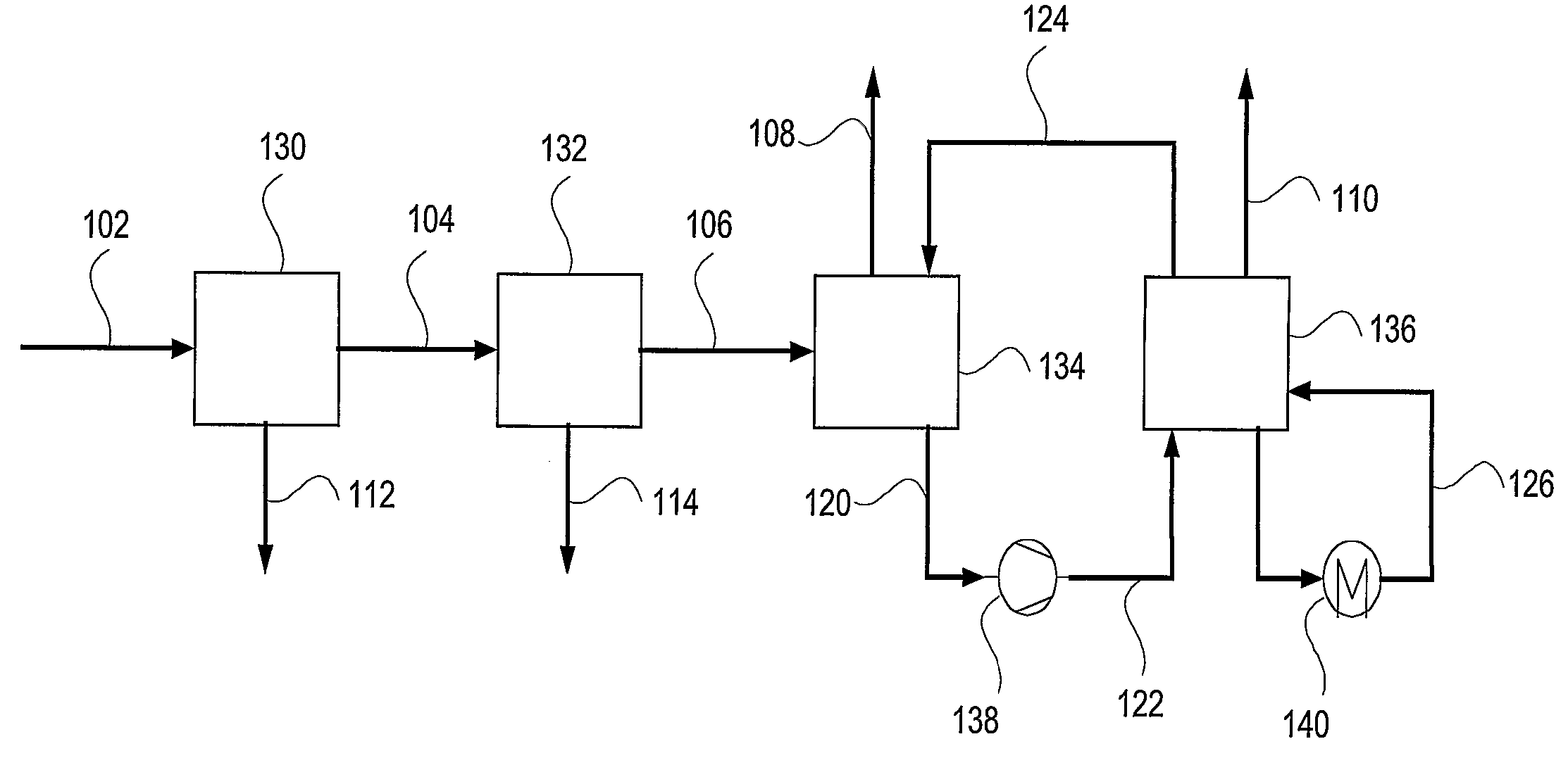
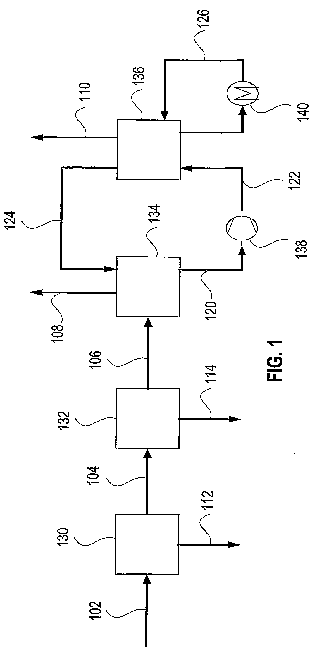
[0032]In accordance with the present invention, a process and system to remove most contaminants, including CO2, from gas streams is provided. These gases are typically resulting from the combustion or gasification of coal, liquid fuels, gaseous fuels and organic waste materials. The contaminants include residual of e.g. SO2, SO3, HCl, HF, CO2, particulate matter including PM2.5, mercury and other volatile matter. The high removal efficiency of the contaminants is achieved by saturation and efficient cooling of the gas to below its adiabatic saturation temperature and preferably to as low as 0-20, or even 0-10, degrees Celsius. Fine particles and acid mist are nucleation sites for the condensation of water. Thus, practically all fine particles and acid mist are removed from the gas stream. The low temperature creates an environment of low vapor pressure of SO2, SO3, HCl, HF, Mercury and other volatile matter, which condense into the cold water as well.

[0033]The cooling of the flue g...


PUM

PropertyMeasurementUnit
temperatureaaaaaaaaaa

Abstract

Ultra cleaning of combustion gas to near zero concentration of residual contaminants followed by the capture of CO2 is provided. The high removal efficiency of residual contaminants is accomplished by direct contact cooling and scrubbing of the gas with cold water. The temperature of the combustion gas is reduced to 0-20 degrees Celsius to achieve maximum condensation and gas cleaning effect. The CO2 is captured from the cooled and clean flue gas in a CO2 absorber (134) utilizing an ammoniated solution or slurry in the NH3—CO2H2O system. The absorber operates at 0-20 degrees Celsius. Regeneration is accomplished by elevating the pressure and temperature of the CO2-rich solution from the absorber. The CO2 vapor pressure is high and a pressurized CO2 stream, with low concentration of NH3 and water vapor is generated. The high pressure CO2 stream is cooled and washed to recover the ammonia and moisture from the gas.

Description

FIELD OF THE INVENTION[0001]The present invention relates to systems and methods for ultra cleaning of combustion gas followed by the capture and regeneration of CO2.BACKGROUND[0002]Most of the energy used in the world today is derived from the combustion of carbon and hydrogen containing fuels such as coal, oil and natural gas. In addition to carbon and hydrogen, these fuels contain oxygen, moisture and contaminants such as ash, sulfur, nitrogen compounds, chlorine, mercury and other trace elements. Awareness to the damaging effects of the contaminants released during combustion triggers the enforcement of ever more stringent limits on emissions from power plants, refineries and other industrial processes. There is an increased pressure on operators of such plants to achieve near zero emission of contaminants and to reduce CO2 emission.[0003]The art teaches various processes and technologies designed to reduce the emission of contaminants from combustion gases. Baghouses, electrost...

Claims


Application Information

Patent Timeline
Patent Type & Authority Patents(United States)
IPC IPC(8): B01D53/14
CPCB01D53/1475B01D53/62B01D53/75F23J15/06F23J15/006B01D2251/2062B01D2252/102Y02E20/326F23J2215/50F23J2219/50Y02C10/04Y02C10/06Y02C20/40B01D53/14Y02A50/20Y02E20/32
Inventor GAL, ELI
Owner GENERAL ELECTRIC TECH GMBH
Why Eureka
Try Eureka