Cleaning method, cleaning apparatus, and liquid ejecting apparatus
一种清洗装置、液体喷射头的技术,应用在引用其全部内容领域,能够解决破坏等问题
- Summary
- Abstract
- Description
- Claims
- Application Information
AI Technical Summary
Problems solved by technology
Method used
Image
Examples
no. 1 approach
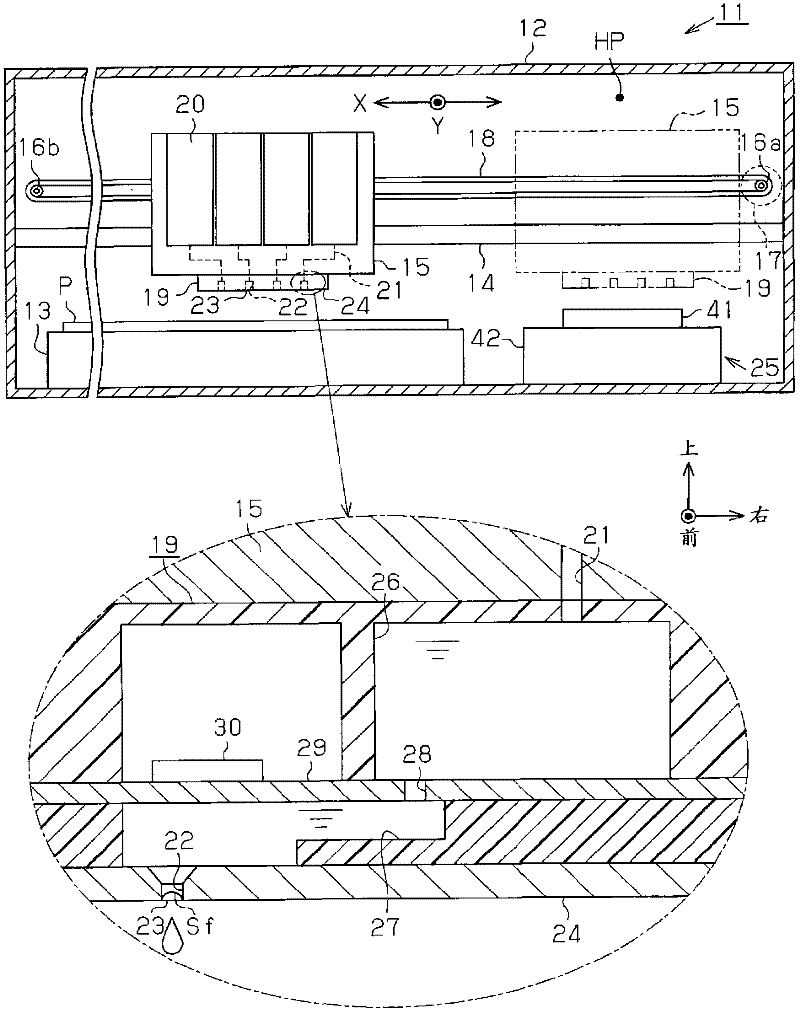
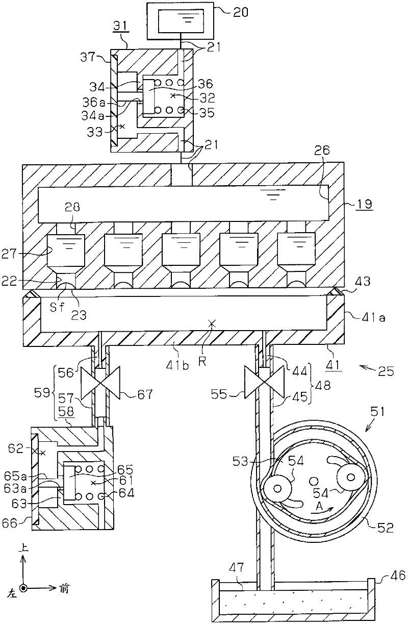
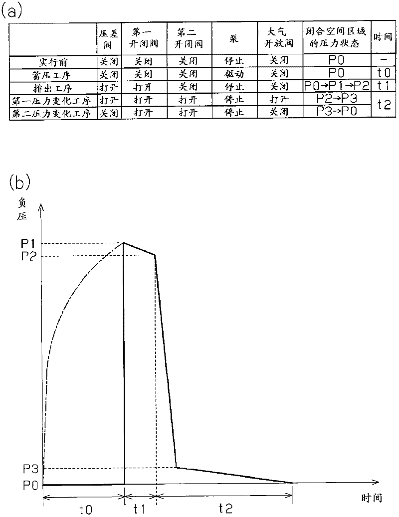
[0055] Below, based on Figure 1 ~ Figure 4 A first embodiment of the present invention will be described as an inkjet printer (hereinafter also referred to as a “printer”) which is one type of liquid ejecting apparatus. In addition, in the following description, when referring to "front-rear direction", "up-down direction" and "left-right direction", unless otherwise specified, they refer to "front-rear direction", "up-and-down direction" indicated by arrows in each figure, unless otherwise specified. Direction" and "Left-Right Direction". In this case, the direction from the back side to the front side of the "front-back direction" in this case corresponds to the conveyance direction (sub-scanning direction) of the recording medium, the "up-down direction" corresponds to the vertical direction, and the "left-right direction" corresponds to The width direction (main scanning direction) intersecting with the conveyance direction of the recording medium.
[0056] Such as fig...
no. 2 approach
[0100] Next, based on Figure 5 as well as Image 6 A second embodiment of the present invention will be described. In addition, when comparing the second embodiment with the first embodiment, the structure of the cleaning device 25 is partially different, and the other is substantially the same structure as the first embodiment. Therefore, in the following, points different from the first embodiment will be mainly described, and the same reference numerals will be attached to the same configurations, and repeated descriptions will be omitted.
[0101] Such as Figure 5 As shown, in the cleaning device 25 of the second embodiment, the front end side of the inflow hose 57 constituting a part of the inflow channel 59 is released to the atmosphere. In addition, in the inflow hose 57 , a pump 71 is arranged between the front end side of the inflow hose 57 and the second on-off valve 67 instead of the atmosphere release valve 58 . The pump 71 is a hose pump having substantially...
no. 3 approach
[0119] Next, based on Figure 7 as well as Figure 8 A third embodiment of the present invention will be described. In addition, the third embodiment differs in part from the first and second embodiments in the configuration of the cleaning device 25 , and has substantially the same configuration as the first and second embodiments. Therefore, in the following, points different from those of the first and second embodiments will be mainly described, and the same reference numerals will be assigned to the same configurations, and repeated descriptions thereof will be omitted.
[0120] Such as Figure 7 As shown, in the cleaning device 25 according to the third embodiment, the pump 81 which is the same hose pump is disposed in the middle of the discharge flow path 48 and the inflow flow path 59 .
[0121] That is, the pump 81 has a pump casing 82 formed in a substantially cylindrical shape, and in the pump casing, the middle portion of the discharge hose 45 in the longitudina...
PUM
 Abstract
Description
Claims
Application Information
 - R&D
- Intellectual Property
- Life Sciences
- Materials
- Tech Scout
- Unparalleled Data Quality
- Higher Quality Content
- 60% Fewer Hallucinations
Browse by: Latest US Patents, China's latest patents, Technical Efficacy Thesaurus, Application Domain, Technology Topic, Popular Technical Reports.
© 2025 PatSnap. All rights reserved.Legal|Privacy policy|Modern Slavery Act Transparency Statement|Sitemap|About US| Contact US: help@patsnap.com


