Seat back structure of vehicle seat and method for inhibiting head tremor damage for seat back of vehicle seat

A technology for seat backs and vehicles, which is applied to vehicle seats, vehicle parts, special positions of vehicles, etc., can solve the problems of occupants easily feeling the bottom, and the elastic deformation of support plates is limited, etc., and achieves excellent applicability and parts. The effect of reducing the number of objects and simplifying the structure and miniaturization

Inactive Publication Date: 2015-07-22
TACHI S CO LTD
View PDF9 Cites 0 Cited by
  • Summary
  • Abstract
  • Description
  • Claims
  • Application Information

AI Technical Summary

Problems solved by technology

Therefore, if the pressure-receiving member is arranged directly behind the support plate, although the pressure-receiving member can quickly withstand the impact load and be displaced, the elastic deformation of the support plate elastically supporting the back of the occupant is restricted, and the occupant is likely to feel a bottoming feeling.

Method used


Image

  • Seat back structure of vehicle seat and method for inhibiting head tremor damage for seat back of vehicle seat
  • Seat back structure of vehicle seat and method for inhibiting head tremor damage for seat back of vehicle seat
  • Seat back structure of vehicle seat and method for inhibiting head tremor damage for seat back of vehicle seat

Examples


Embodiment 1

[0049] Hereinafter, embodiments of the present invention will be described in detail with reference to the drawings.

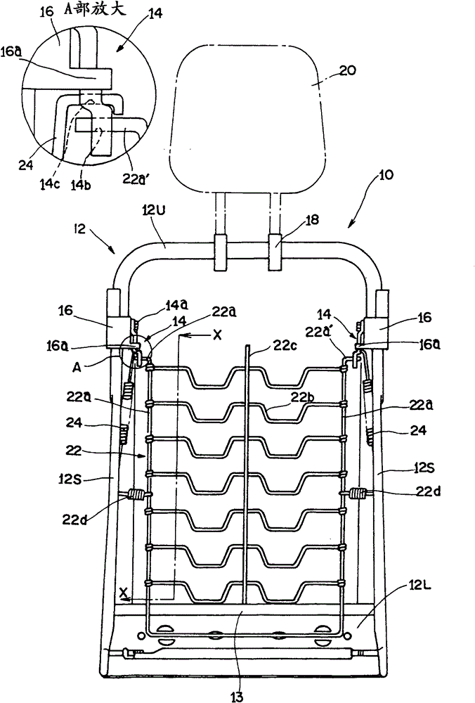
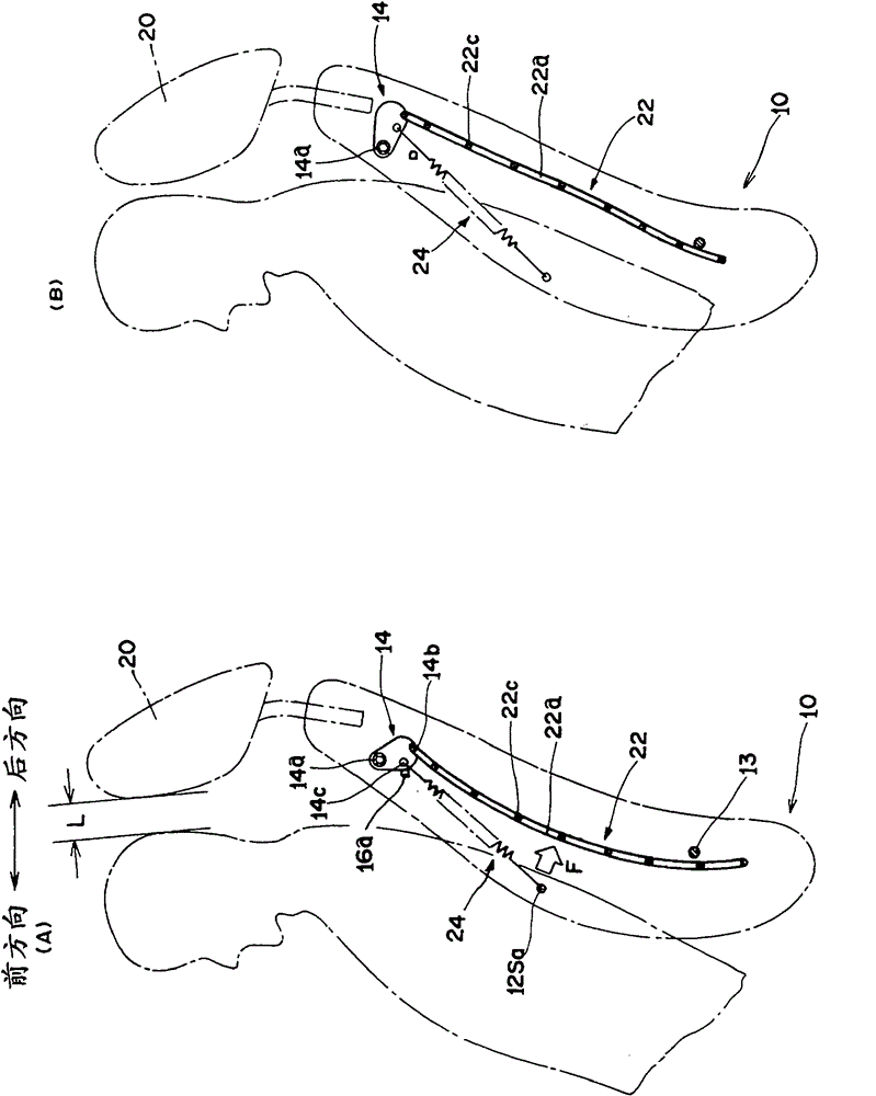
[0050] figure 1 It is a schematic front view showing a seat back structure of an embodiment of the present invention. in addition, figure 2 (A), (B) represent along figure 1 The movement of the main components before and after the application of the impact load on the cross section of the line X-X in , and the components not related to the movement of the support plate are omitted to avoid complicating the drawing.

[0051] Such as figure 1 As shown, in the seat back 10 of the vehicle seat of the present invention, the seat back frame 12 has a substantially inverted U-shaped upper portion composed of a pair of left and right side members 12S and pipes connecting the left and right side members above. The member 12U and the lower member 12L connecting the left and right side members below are formed in a rectangular frame shape. Furthermore, a pair of tur...

Embodiment 2

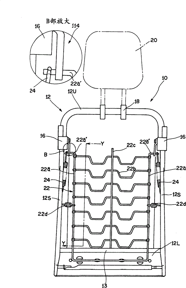
[0087] image 3 , Figure 4 The seat back structure of another example (Example 2) is shown. here, image 3 , Figure 4 With above-mentioned embodiment (embodiment 1) figure 1 , figure 2 (A), (B) corresponding, image 3 A schematic front view showing the seat back structure of Embodiment 2, Figure 4 (A), (B) represent along image 3 The movement of the main constituent parts before and after the impact load is applied on the cross-section of the line Y-Y. In addition, in Figure 4 (A), (B), and figure 2 (A) and (B) Similarly, components not related to the movement of the support plate are omitted to avoid complicating the drawings.

[0088] In Embodiment 1, the left and right frames of the supporting plate move backward with the rotation of the rotating link, but in Embodiment 2, the following point is different in that a guide hole with a guide hole is provided instead of the rotating link. Fixed guide plate, the frame body upper end of support plate can move a...


PUM


Abstract

The invention discloses a seat back structure of a vehicle seat and a method for inhibiting head tremor damage for a seat back of the vehicle seat. The invention provides the seat back structure for the vehicle seat. In the past, a pressure part is arranged behind a support plate, and a transfer part used for transferring displacement of the pressure part to rotating connecting rods is arranged behind the support part, thus many parts are needed. One pair of rotating connecting rods can be rotatably arranged on a left side member and a right side member of a seat back frame in a manner of limiting towards rotation, the left end and the right end of the support plate are provided with a frame body extending along the upper direction and the lower direction, and the upper end of the frame body is connected to the rotating connecting rods. Because a drawing coil spring which can be lengthened due to a collision load during colliding is erected between the side members and the rotating connecting rods, an elastic force of the drawing coil spring is applied to the support plate through the rotating connecting rods for limiting the rotation of the rotating connecting rods when backward collision does not exist. During backward collision, the support plate resists the elastic force of the drawing coil spring to ensure that the rotating connecting rods rotate and moves backwards, thus a passenger greatly sinks into the seat back and the head of the passenger moves in close to a displacement-free headrest.

Description

technical field [0001] The present invention relates to a seat back structure of a vehicle seat and a method for suppressing head vibration damage in the seat back of a vehicle seat, wherein a headrest and a headrest are adjusted according to a collision load acting on an occupant in a rear collision The gap between the occupant's head is narrowed to suppress head vibration damage. Background technique [0002] There is known a structure in which the headrest is kept at the normal support position, that is, the initial position below by the force applied by the urging mechanism composed of a tension coil spring or the like, and when the rear collision occurs, when the occupant inertia When moving and generating a load (collision load), the headrest is forcibly displaced from a lower initial position to an upper displacement position against the force applied by the urging mechanism (for example, JP-A-2007-186103). [0003] A head restraint that forcibly displaces from a low...

Claims


Application Information

Patent Timeline
Patent Type & Authority Patents(China)
IPC IPC(8): B60N2/68B60N2/42
Inventor 神田健司
Owner TACHI S CO LTD
Why Eureka
Try Eureka