Tube cutter for glass tube

A glass lamp tube and tube cutting machine technology, applied in glass cutting devices, glass manufacturing equipment, manufacturing tools, etc., can solve the problems of broken glass tubes, low efficiency, unstable product quality, etc. The effect of inaccurate length and not easy to break

Active Publication Date: 2012-07-04
ANHUI SHILIN LIGHTING
View PDF4 Cites 11 Cited by
  • Summary
  • Abstract
  • Description
  • Claims
  • Application Information

AI Technical Summary

Problems solved by technology

[0002] In the production process of fluorescent lamps, a large number of glass tube sections are required. The glass tube sections are obtained by cutting the glass tube into small pieces. When cutting, the glass tube must be cut to length first. Continue to cut, like this, glass tube section just is cut off, and the existing work of dividing glass lamp tube is to carry out manually, not only efficiency is low, and product quality is unstable, and, easily make glass tube broken because of operator's mistake

Method used


Image

  • Tube cutter for glass tube
  • Tube cutter for glass tube
  • Tube cutter for glass tube

Examples


Embodiment Construction

[0013] Below in conjunction with accompanying drawing, specific embodiment of the present invention is described in further detail:

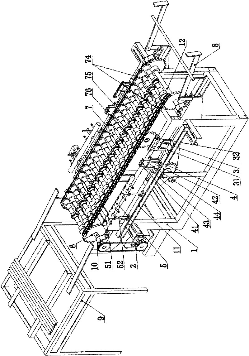
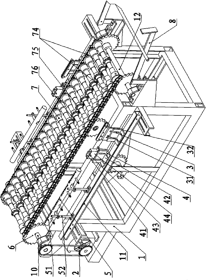
[0014] Such as figure 1 , figure 2 As shown, the glass lamp tube cutting machine of the present invention includes a frame 1, a transmission device 2, a cutting fire device 3, a cutter device 4, a round mouth fire device 5, a driving sprocket 6, a lamp tube rotation and translation device 7, an upper tube The pipe rack 8 and the lower pipe placement rack 9; wherein, the frame 1 is a cuboid, and its two ends are respectively equipped with a driving shaft 10 and a driven shaft 12, and the transmission device 2 is installed on the left lower side of the frame 1, and passes through The sprocket transmission pair is connected with the driving shaft 10 to drive the machine to run. A group of driving sprockets 6 are respectively installed at the two ends of the driving shaft 10 and the driven shaft 12, and are respectively connected to each other thr...


PUM


Abstract

The invention relates to a tube cutter for a glass tube, which is characterized in that a frame is cuboid and a drive shaft and a driven shaft are respectively arranged at both ends of the frame. A transmission device is arranged bottom left of the frame and connected with the drive shaft through a chain wheel transmission pair. Two sets of drive chain wheels are respectively arranged at both ends of the drive shaft and the driven shaft and connected with each other through two parallel transmission chains. An upper tube placing frame is arranged at one side of the driven shaft while a lower tube placing frame is arranged at one side of the drive shaft. A tube rotary translation device is arranged between the two transmission chains. Groove frames are respectively arranged at both sides of the frame from the driven shaft to the drive shaft. A cutting fire device, a cutting knife device and a round mouth fire device are arranged on the groove frame in sequence. The cutting fire device,the cutting device and the round mouth fire device are respectively installed on the frame in a symmetrical manner. Compared with the prior art, the tube cutter of the invention realizes the refine operation of glass tube cutting step, overcomes inaccuracy of fixed cutting length and cracking or crushing of the glass tube in the prior art, and has the advantages of high production efficiency, stable quality of product and difficulty in breaking the glass tube and the like.

Description

Technical field: [0001] The invention relates to a fluorescent lamp production equipment, in particular to a glass lamp tube cutting machine. Background technique: [0002] In the production process of fluorescent lamps, a large number of glass tube sections are required. The glass tube sections are obtained by cutting the glass tube into small pieces. When cutting, the glass tube must be cut to length first. Continue to cut, like this, glass tube section just is cut off, and the work of existing division glass lamp tube is to carry out manually, not only efficient is low, and product quality is unstable, and, easily makes glass tube broken because of operator's mistake. Invention content: [0003] The technical problem to be solved by the present invention is to provide a glass lamp tube cutting machine with simple cutting method, high production efficiency, stable product quality and unbreakable glass tube against the above-mentioned shortcomings of the prior art. [00...

Claims


Application Information

Patent Timeline
Patent Type & Authority Applications(China)
IPC IPC(8): C03B33/06
Inventor 吴百超许梅
Owner ANHUI SHILIN LIGHTING
Why Eureka
Try Eureka