Zoom lens

A zoom lens and lens barrel technology, applied in the field of zoom lenses, can solve the problem of the mirror chamber being unable to maintain a stable position, and achieve the effect of increasing stability

Inactive Publication Date: 2012-07-04
ASIA OPTICAL CO INC
View PDF3 Cites 0 Cited by
  • Summary
  • Abstract
  • Description
  • Claims
  • Application Information

AI Technical Summary

Problems solved by technology

[0005] Therefore, the technical problem to be solved by the present invention is to provide a zoom lens whose overall structure can be relatively stable when it is actuated, aiming at the defect that each mirror chamber in the zoom lens in the prior art cannot maintain a stable position.

Method used


Image

  • Zoom lens
  • Zoom lens
  • Zoom lens

Examples


Embodiment Construction

[0016] In order to describe in detail the structure, features and effects of the present invention, a preferred embodiment is enumerated and described as follows in conjunction with the accompanying drawings, wherein:

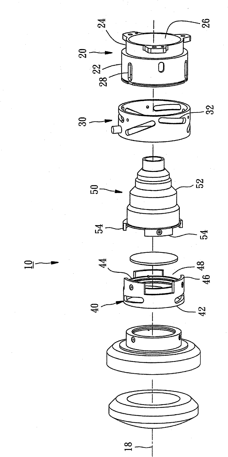
[0017] figure 1 It is an exploded perspective view of a preferred embodiment of the present invention.

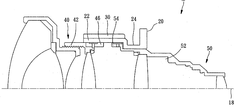
[0018] figure 2 It is a partial sectional view of a preferred embodiment of the present invention, wherein the first mirror chamber and the second mirror chamber are separated from each other.

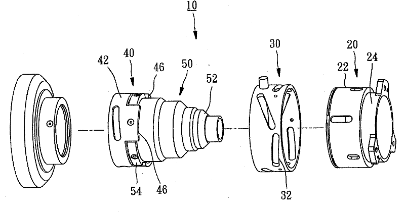
[0019] image 3 It is a three-dimensional partial exploded view of a preferred embodiment of the present invention, wherein the fitting portion of the first mirror chamber is inserted into the fitting groove of the second mirror chamber.

[0020] Figure 4 It is a partial cross-sectional view of a preferred embodiment of the present invention, wherein the fitting portion of the first mirror chamber is inserted into the slot of the second mirror chamber.

[002...


PUM


Abstract

The present invention relates to a zoom lens comprising a fixed base, a driving wheel and at least two lens chambers; wherein the fixed base is provided with a containing hole extending along an optical axis; the driving wheel takes the optical axis as an axle center and is rotatably arranged on the fixed base; the lens chambers are movably arranged in the containing hole of the fixed base along the optical axis; and at least one lens chamber is connected with the driving wheel. By adopting the above structure, when the driving wheel rotates relative to the fixed base, the lens chambers can be driven to close to or separate from each other in the fixed base, thereby achieving the effect that the integral structure is stable during moving.

Description

technical field [0001] The invention relates to a lens, in particular to a zoom lens. Background technique [0002] The development of digital imaging technology is changing with each passing day. In addition to the pursuit of high-pixel imaging and high-resolution output, electronic devices equipped with digital imaging must also have technical characteristics such as faster operation speed and smaller size. For example, equipment such as digital cameras or projectors, in order to be convenient for operators to use in various environments, it is often necessary to achieve a design that minimizes the volume and maximizes the performance. [0003] The lenses of existing digital cameras or projectors and other equipment usually have the function of adjusting the focal length, such as Figure 5 and Figure 6 As shown, the known lens usually has a front group mirror chamber 72 and a rear group mirror chamber 74 arranged in the fixed seat 70, and the two mirror chambers 72, 74 a...

Claims


Application Information

Patent Timeline
Patent Type & Authority Applications(China)
IPC IPC(8): G02B7/10
Inventor 江志豪
Owner ASIA OPTICAL CO INC
Why Eureka
Try Eureka