Head-mounted display

A display and head-mounted technology, applied in the field of head-mounted displays, can solve problems such as the difficulty for users to adjust the interpupillary distance

Inactive Publication Date: 2012-07-04
SONY CORP
View PDF9 Cites 13 Cited by
  • Summary
  • Abstract
  • Description
  • Claims
  • Application Information

AI Technical Summary

Problems solved by technology

[0007] However, in the method in which the outside observer adjusts the interpupillary distance,

Method used


Image

  • Head-mounted display
  • Head-mounted display
  • Head-mounted display

Examples


Embodiment Construction

[0029] Embodiments of the present technology will be described in detail with reference to the drawings.

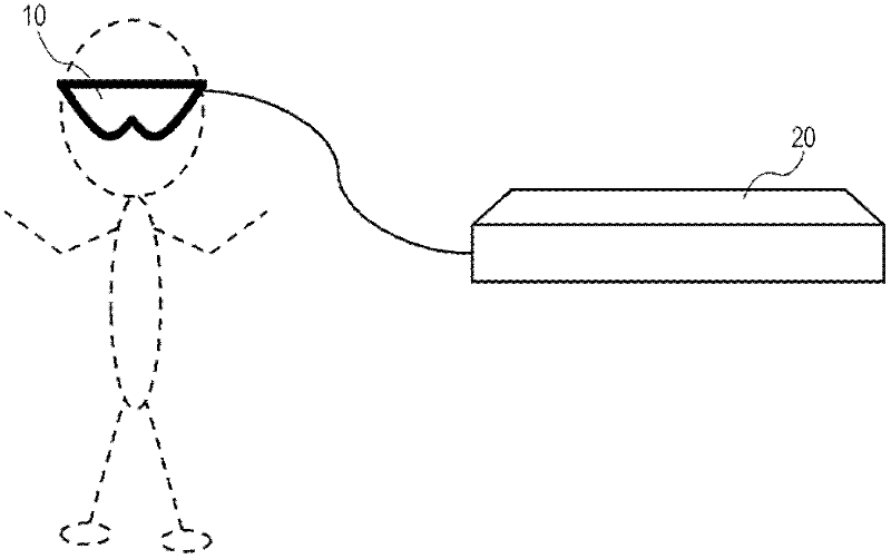
[0030] figure 1 A configuration of an image display system including a head-mounted display is schematically illustrated. figure 1 The system shown consists of the main body of the head mounted display 10 and the Blu-ray Disc reproduction device 20 which is the source of viewing content.

[0031] The Blu-ray disc reproduction device 20 and the head-mounted display 10 (ie, the front-end box 40 and the high-definition display 30 ) are connected by a high-definition multimedia interface (HDMI) cable. The Blu-ray Disc reproduction device 20 performs reproduction processing of video / audio data recorded in a loaded Blu-ray Disc (not shown), and performs HDMI output of the video / audio data. Here, HDMI is an interface standard formed based on digital visual interface (DVI), including a physical layer of transition minimized differential signaling (TMDS), and used for digital ho...


PUM


Abstract

A head-mounted display includes a left-eye display unit configured to display a left-eye image, a right-eye display unit configured to display a right-eye image, a display control unit configured to control screen display of the left-eye display unit and the right-eye display unit, and an interpupillary distance adjustment mechanism configured to adjust an interpupillary distance between the left-eye display unit and the right-eye display unit. In the head-mounted display, the display control unit allows the left-eye display unit and the right-eye display unit to display a signal pattern for interpupillary distance adjustment when the interpupillary distance is adjusted by the interpupillary distance adjustment mechanism.

Description

technical field [0001] The present technology relates to a head-mounted display that is used to be mounted on a user's head. Specifically, the present technology relates to a head-mounted display including an interpupillary distance adjustment mechanism for precisely setting the head-mounted display to correspond to the interpupillary distance of a user wearing the head-mounted display. Background technique [0002] A 3D image that can be viewed three-dimensionally can be provided to an observer by displaying images having parallax for the observer's right and left eyes. It has been anticipated that 3D image technology will be applied to various fields such as television broadcasting, movies, telecommunications, and telemedicine. For example, a time-division stereoscopic image display system composed of a combination of a display device and 3D glasses has been widely spread (for example, refer to Japanese Unexamined Patent Application Publication No. 2010-21731). The displ...

Claims


Application Information

Patent Timeline
IPC IPC(8): G02B27/01
CPCH04N13/0425H04N2213/001H04N13/044G02B7/12G02B27/0176H04N13/344H04N13/327
Inventor 清水将之
Owner SONY CORP
Why Eureka
Try Eureka