Magnetic induction coil moving non-contact charger

A magnetic induction, mobile technology, applied in the direction of collectors, electric vehicles, electrical components, etc., can solve the problem that the distance between the power coil and the induction coil cannot be kept constant, the distance between the power coil and the induction coil cannot be kept constant, and it is difficult to realize the power High efficiency and other issues, to achieve the effect of improved slidability, simplified structure, low cost and simplification

Inactive Publication Date: 2012-07-11
德利信电子有限公司
View PDF4 Cites 11 Cited by
  • Summary
  • Abstract
  • Description
  • Claims
  • Application Information

AI Technical Summary

Problems solved by technology

However, the requirement for high precision parts cannot be alleviated, and the high precision requirements for parts will increase the price of parts. At the same time, the distance between the power supply coil and the induction coil cannot be kept constant, and it is difficult to achieve high power efficiency.
In addition, in the above, the case

Method used


Image

  • Magnetic induction coil moving non-contact charger
  • Magnetic induction coil moving non-contact charger
  • Magnetic induction coil moving non-contact charger

Examples


Embodiment Construction

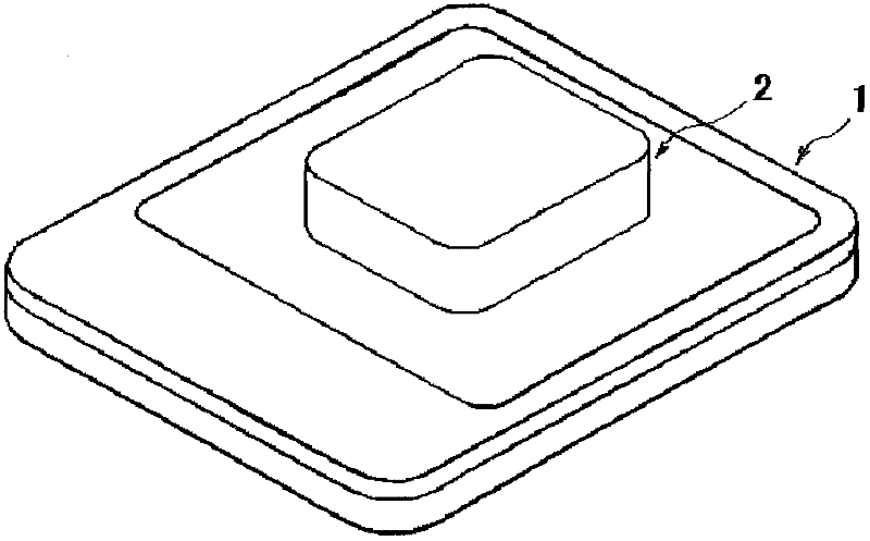
[0049] Hereinafter, preferred embodiments for carrying out the present invention will be described with reference to the drawings. figure 1 It is a side view showing the external appearance of the magnetic induction type coil moving non-contact charger 1 of the present invention and a rechargeable battery 2 used as a power source equipped with a power receiving coil in electronic equipment or the like.

[0050] This non-contact charger 1 does not need to connect the charger side and the rechargeable battery side with terminals or the like, but instead figure 1 As shown, as long as the rechargeable battery 2 is placed on the charger 1, the power of the charger 1 can be transmitted to the rechargeable battery 2 and the rechargeable battery 2 can be charged in a non-contact manner. Coils are provided on the side of the charger and the side of the rechargeable battery, and these coils are used to transmit the power of the charger to the rechargeable battery and charge the rechar...


PUM


Abstract

The invention provides a magnetic induction coil moving non-contact charger. The magnetic induction coil moving non-contact charger is simple in structure, low in cost and high in electric efficiency. The magnetic induction coil moving non-contact charger makes a table equipped with a transmission coil to move freely in an X-axis direction and a Y-axis direction. In the magnetic induction coil moving non-contact charger, an enabling component is included between a sliding base and the table. The transmission coil is pressed on a circuit substrate by utilizing an addition force of the enabling component and the table moves in the X-axis direction and the Y-axis direction.

Description

technical field [0001] The present invention relates to a magnetic induction type coil moving non-contact charger with simple structure, low price, high electrical efficiency and excellent durability, in which a rechargeable battery with built-in power receiving side coil is placed on it, so that the power transmission device installed The stage of the side coil moves freely in the X-axis direction and the Y-axis direction, and transmits electric power to the power receiving side coil by magnetic induction. Background technique [0002] Various proposals have been made as a magnetic induction type coil moving type non-contact charger in which a table on which a power transmission side coil is mounted can be freely moved in the X-axis direction and the Y-axis direction. [0003] For example, JP-A-2009-247194 discloses the following charging stand. [0004] That is, in this publication, the following components are provided: a power coil (11) connected to an AC power source (...

Claims


Application Information

Patent Timeline
IPC IPC(8): H02J7/00H02J17/00
Inventor 山中隆
Owner 德利信电子有限公司
Why Eureka
Try Eureka