
End plate, and rotor for rotary electric machine which employs the end plate

A technology of rotating electrical machines and end plates, which is applied in the directions of electromechanical devices, electrical components, and electric components, etc., can solve the problem of increasing eddy current loss, and achieve the effect of suppressing eddy current loss and short circuit of magnetic flux through the end plate.

Inactive Publication Date: 2012-07-11
TOYOTA JIDOSHA KK
View PDF8 Cites 11 Cited by
  • Summary
  • Abstract
  • Description
  • Claims
  • Application Information

AI Technical Summary

Problems solved by technology

That is, since the end plate made of a magnetic material is in contact with the permanent magnet at the inner surface of the through hole formed in the end plate, a large amount of magnetic flux generated by the end portion of the permanent magnet flows into the end plate, Make the eddy current loss become larger

Method used


Image

  • End plate, and rotor for rotary electric machine which employs the end plate
  • End plate, and rotor for rotary electric machine which employs the end plate
  • End plate, and rotor for rotary electric machine which employs the end plate

Examples


Embodiment Construction

[0024] Hereinafter, embodiments of the present invention will be described in detail with reference to the accompanying drawings. In the following description, the specific shapes, materials, values, directions, etc. are only illustrations to facilitate the understanding of the present invention, and can be changed as appropriate according to the application, purpose, specific requirements, etc.

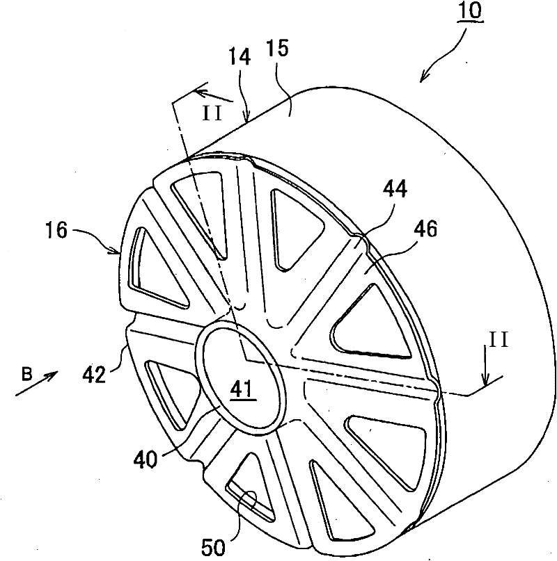
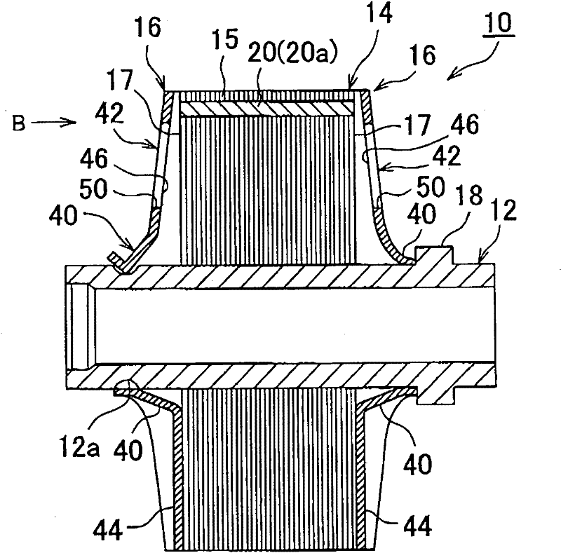
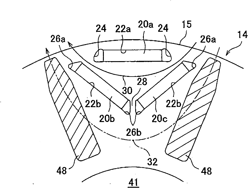
[0025] figure 1 is a perspective view showing a rotor 10 for a rotary electric machine including an end plate 16 of an embodiment of the present invention omitting a diagram of a rotor shaft. figure 1 Only the end plate 16 provided on one of the sides of the rotor 10 in the axial direction of the rotor 10 is shown. also, figure 2 is a sectional view of the rotor 10 including a diagram of the rotor shaft 12 and taken along the axial direction of the rotor 10 . In the following description, the direction along the rotation center axis of the rotor shaft 12 is referred to as the "ax...


PUM


Abstract

An end plate (16) is made of a magnetic material, and holds an axis-direction end surface of a rotor core (14) in which a permanent magnet (20) is buried. The end plate includes: a protruded portion (44) constructed so as to be caused to pressingly contact the axis-direction end surface of the rotor core (14) when mounted in the rotor (10); and a depressed portion (46) constructed so as not to contact the axis-direction end surface (17). The protruded portion (44) is formed so as to contact only one of a d-axis magnetic path region and a q-axis magnetic path region that are formed by the permanent magnet (20) within the rotor core (14).

Description

technical field [0001] The present invention relates to an end plate, and more particularly to an end plate for use in an embedded permanent magnet type rotor of a rotating electrical machine. Background technique [0002] There are known rotating electric machines such as electric motors, generators, etc., each of which includes a rotatably supported embedded magnet type rotor, and a hollow cylindrical stator arranged around the rotor, wherein the rotor is formed of A rotating magnetic field within the stator is rotationally driven. [0003] A rotor generally includes a rotor shaft and a cylindrical rotor core fixed to the rotor shaft. In some cases, a rotor core is formed as a steel plate lamination in which many magnetic steel plates are laminated, and is fixed to a rotor shaft by a method such as swaging. [0004] In the vicinity of the outer peripheral surface of the rotor core, permanent magnets embedded in the rotor core are disposed equidistantly in the inner porti...

Claims


Application Information

Patent Timeline
Patent Type & Authority Applications(China)
IPC IPC(8): H02K1/28H02K1/27
CPCH02K1/2766H02K1/28
Inventor 山岸义忠鹈饲须彦
Owner TOYOTA JIDOSHA KK
Learn More