Single-axis linear movement trace vibration exciter
A technology of linear motion and vibration exciter, applied in chemical instruments and methods, fluid and solid separation using vibration, etc., can solve problems such as error-prone and inconvenient, and achieve easy transformation, convenient use and maintenance, and easy realization. Effect
- Summary
- Abstract
- Description
- Claims
- Application Information
AI Technical Summary
Problems solved by technology
Method used
Image
Examples
Embodiment 1
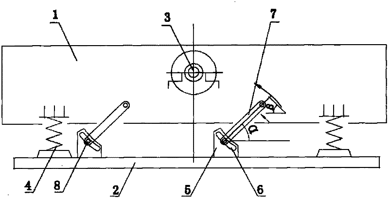
[0029] Embodiment 1: as figure 1 As shown, a single-axis linear motion track exciter includes a vibration box 1, a base 2, an exciting spring 4 and an exciting shaft 3, and the exciting shaft 3 is arranged on the vibration box 1; the exciting spring 4 is set On the four corners between the vibration box 1 and the base 2.
[0030] The vibration box 1 is provided with two pairs of rail-fixing rods, and each pair of rail-fixing rods is symmetrically arranged on both sides of the vibration box 1 (the rail-fixing rod 7 is a fixed rod whose length is stretchable and non-adjustable), and is located on the same side of the vibration box 1. The rail-fixing rods 7 on the top are arranged symmetrically with the longitudinal line where the fixed axis of the excitation shaft 3 is located.
[0031] The upper end of the track rod 7 is hinged on the vibrating box 1, and the lower end is hinged on the base 2. The base 2 is provided with a base 5, the base 5 is provided with an arc-shaped slo...
Embodiment 2
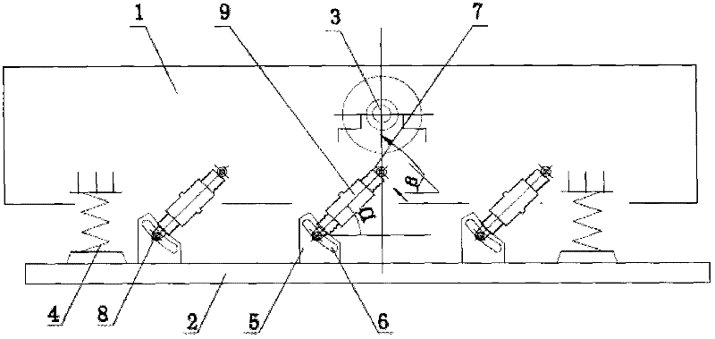
[0034] Embodiment 2: as figure 2 As shown, three pairs of rail-fixing rods are arranged on the vibration box 1, and each pair of rail-fixing rods is symmetrically arranged on both sides of the vibration box 1 (the rail-fixing rod 7 is a telescopic rod with adjustable length, and the telescopic rod includes two sections of threads Screw mandrels in opposite directions and a screw sleeve (9) that connects the two sections of screw mandrels together;
[0035] The rail-fixing rod 7 upper end screw sleeve 9 that is in the middle position among the rail-fixing rods 7 on the same side of the vibration box 1 is arranged on the longitudinal line where the excitation axis 3 is fixed, and the other rail-fixing rods 7 are located on the axis of the excitation shaft. 3 The longitudinal line where the fixed axis is located is arranged symmetrically. All the other are with embodiment 1.
Embodiment 3
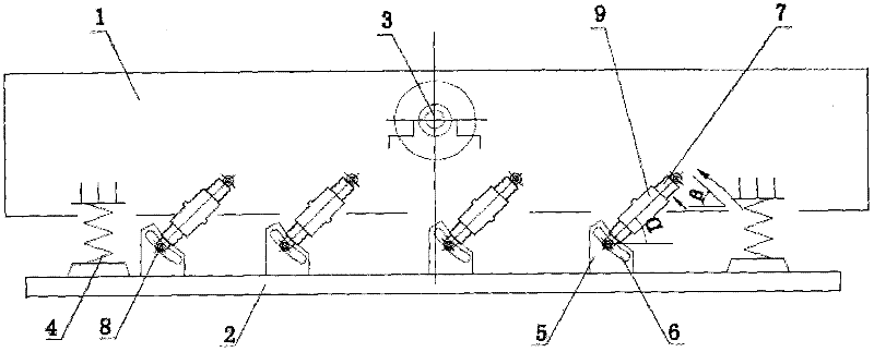
[0036] Embodiment 3: as image 3 As shown, the vibrating box 1 is provided with four pairs of rail-fixing rods, and each pair of rail-fixing rods is arranged symmetrically on both sides of the vibration box 1 (the rail-fixing rod 7 is a telescopic rod whose length is telescopic and adjustable, and the telescopic rod includes two sections The screw mandrel that screw thread direction is opposite and this two section screw mandrels are connected together a screw sleeve 9);
[0037] The rail-determining rods 7 on the same side of the vibrating box body 1 are arranged symmetrically with the longitudinal line where the fixed axis of the excitation shaft 3 is located. All the other are with embodiment 1.
PUM
 Abstract
Description
Claims
Application Information
 - R&D Engineer
- R&D Manager
- IP Professional
- Industry Leading Data Capabilities
- Powerful AI technology
- Patent DNA Extraction
Browse by: Latest US Patents, China's latest patents, Technical Efficacy Thesaurus, Application Domain, Technology Topic, Popular Technical Reports.
© 2024 PatSnap. All rights reserved.Legal|Privacy policy|Modern Slavery Act Transparency Statement|Sitemap|About US| Contact US: help@patsnap.com


