
Uniaxial elliptic motion trail vibration exciter

An elliptical motion and vibration exciter technology, which is applied to chemical instruments and methods, fluids using vibration, solid separation, etc., can solve the problems of complex structure, inconvenient use and maintenance, and high cost of three-axis vibration exciters, and achieve an improvement The effects of excitation effect and efficiency, convenient use and maintenance, and easy transformation

Inactive Publication Date: 2015-06-17
ZHEJIANG SHENGDA MACHINERY
View PDF6 Cites 0 Cited by
  • Summary
  • Abstract
  • Description
  • Claims
  • Application Information

AI Technical Summary

Problems solved by technology

However, the structure of the three-axis vibrator is very complicated, the cost is high, and it is inconvenient to use and maintain (the three-axis vibrator needs to be opened to disassemble the ring gear when adjusting the vibration direction angle, which is extremely inconvenient. It is extremely error-prone when the user adjusts it by himself)

Method used


Image

  • Uniaxial elliptic motion trail vibration exciter
  • Uniaxial elliptic motion trail vibration exciter
  • Uniaxial elliptic motion trail vibration exciter

Examples


Embodiment 1

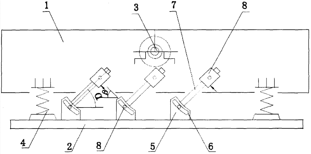
[0026] Example 1: as figure 1 As shown, a uniaxial elliptical motion trajectory vibration exciter includes a vibration box 1, a base 2, an excitation spring 4 and an excitation shaft 3, and the excitation shaft 3 is arranged on the vibration box 1; the excitation spring 4 is provided with On the four corners between the vibration box 1 and the base 2.

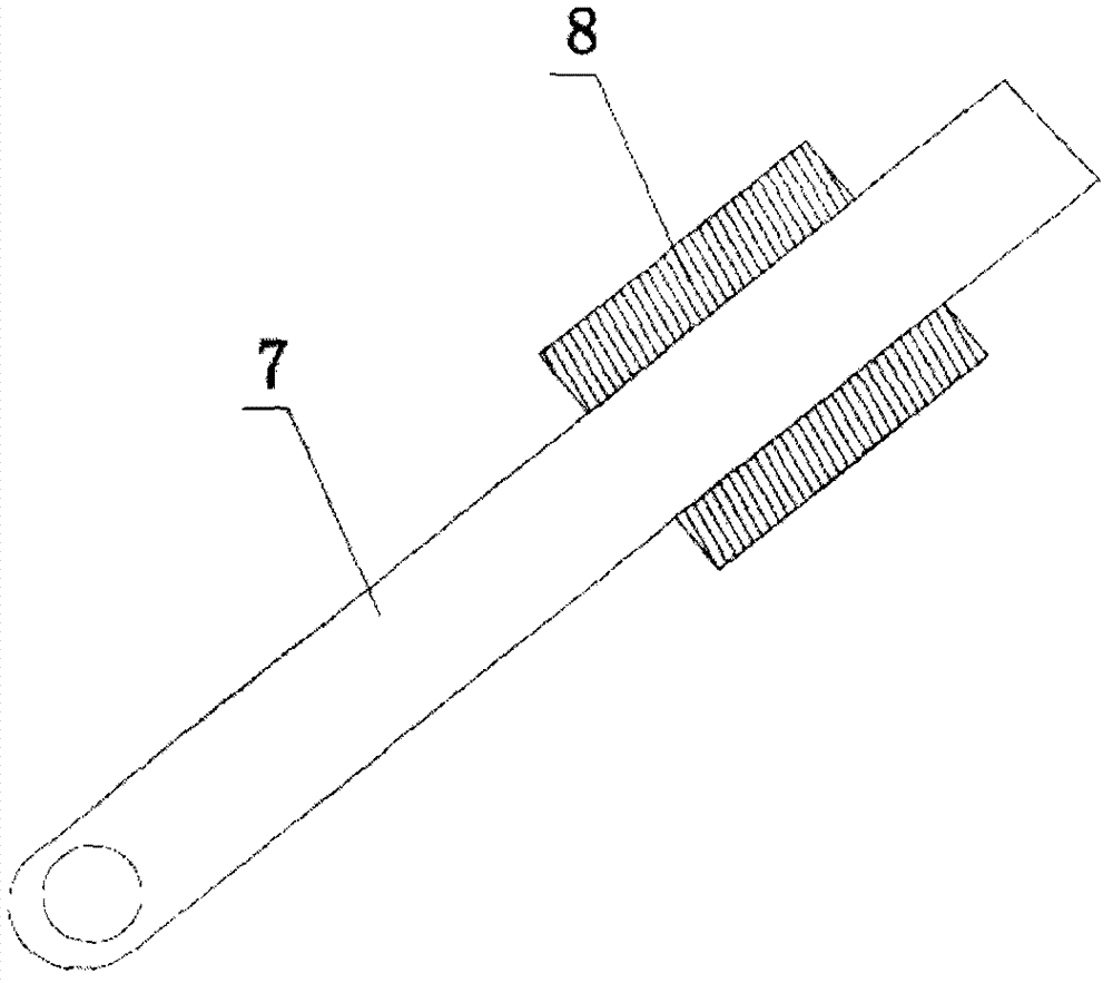
[0027] Three pairs of rail-fixing mechanisms are arranged on the vibration box 1 , and each pair of rail-fixing mechanisms is symmetrically arranged on both sides of the vibration box 1 . The rail fixing mechanism includes a certain rail 7 and a sliding sleeve 8; the upper end of the rail fixing rod 7 is sleeved in the sliding sleeve 8, and the sliding sleeve 8 is hinged on the vibration box 1, such as image 3 shown.

[0028] The lower end of the fixed rail rod 7 is hinged on the base 2, the base 2 is provided with a base 5, the base 5 is provided with an arc-shaped slot 6, and the hinge shaft of the lower end of the fixed-r...

Embodiment 2

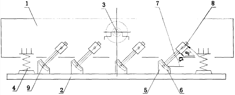
[0032] Example 2: as figure 2 As shown, the vibration box 1 is provided with four pairs of rail-fixing mechanisms, and each pair of rail-fixing mechanisms is symmetrically arranged on both sides of the vibration box 1 . The track-fixing mechanism includes a certain track 7 and a sliding sleeve 8 .

[0033] The rail-fixing rods 7 located on the same side of the vibration box 1 are arranged symmetrically with respect to the longitudinal line where the fixed axis of the excitation shaft 3 is located. The rest are the same as in Example 1.


PUM


Abstract

The invention discloses a uniaxial elliptic motion trail vibration exciter, comprising a vibration box body, a base, a vibration exciting spring and an eccentric shaft, wherein the eccentric shaft is arranged on the vibration box body; the vibration exciting spring is arranged between the vibration box body and the base; the vibration box body is provided with more than two pairs of orbit determination pairs, each pair of orbit determination pair comprises two orbit determination assemblies which are symmetrically arranged at the two sides of the vibration box body; each orbit determination assembly comprises an orbit determination rod and a sliding sleeve; the upper end of the orbit determination rod is sheathed into the sliding sleeve, the sliding sleeve is hinged on the vibration box body, the lower end of each orbit determination rod is hinged on the base, and the orbit determination rods are uniformly obliquely arranged in an array. The uniaxial elliptic motion trail vibration exciter disclosed by the invention has the obvious effects that circular motion trail of a uniaxial vibration exciter is converted into an elliptic motion trail by applying design of the orbit determination rods and the sliding sleeves, and vibration exciting effect and efficiency are enhanced.

Description

technical field [0001] The invention relates to the technical field of vibration machinery, in particular to a vibration exciter assembly applied to two types of equipment, vibrating screen or feeder, in mining machinery, and more particularly to a single-axis elliptical motion trajectory vibration exciter. Background technique [0002] In the crusher industry, the use of a single shaft as a vibration exciter for two types of equipment such as a vibrating screen or a feeder is the most typical structure and is also the most widely used model. [0003] The motion trajectory generated by the uniaxial vibration exciter is a circle, and the circular motion trajectory has both the normal direction vibration component and the tangential direction vibration component. The advantage of this is that the critical material is not easy to block holes on the screen. However, after the circular motion is combined with the spring motion in the vibrating box, the original motion trajectory ...

Claims


Application Information

Patent Timeline
Patent Type & Authority Patents(China)
IPC IPC(8): B06B1/16B07B1/28B07B1/42B02C23/02
Inventor 朱兴良
Owner ZHEJIANG SHENGDA MACHINERY
Learn More