A Rotary Ultrasonic Vibration Device and Time-Temporal Phase Tuning Method

An excitation device and rotating ultrasonic technology are applied in the direction of electrical components, piezoelectric effect/electrostrictive or magnetostrictive motors, generators/motors, etc., and can solve problems affecting stability and work efficiency, operating point drift, Affect the excitation efficiency and other issues to achieve the effect of making up for the drift of the operating point, improving flexibility, and improving the excitation efficiency

Active Publication Date: 2017-06-27
TIANJIN UNIV
View PDF5 Cites 0 Cited by
  • Summary
  • Abstract
  • Description
  • Claims
  • Application Information

AI Technical Summary

Problems solved by technology

In fact, due to the influence of processing and assembly errors, the mass and stiffness distribution of the vibrator usually change, so the working point will drift and affect the excitation efficiency
[0003] If the natural frequency splitting and mode coupling phenomenon caused by the periodicity of the structure are considered, the fluctuations on the surface of the vibrator will be distorted, which will affect the stability and work efficiency

Method used


Image

  • A Rotary Ultrasonic Vibration Device and Time-Temporal Phase Tuning Method
  • A Rotary Ultrasonic Vibration Device and Time-Temporal Phase Tuning Method
  • A Rotary Ultrasonic Vibration Device and Time-Temporal Phase Tuning Method

Examples


Embodiment 1

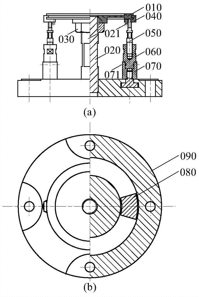
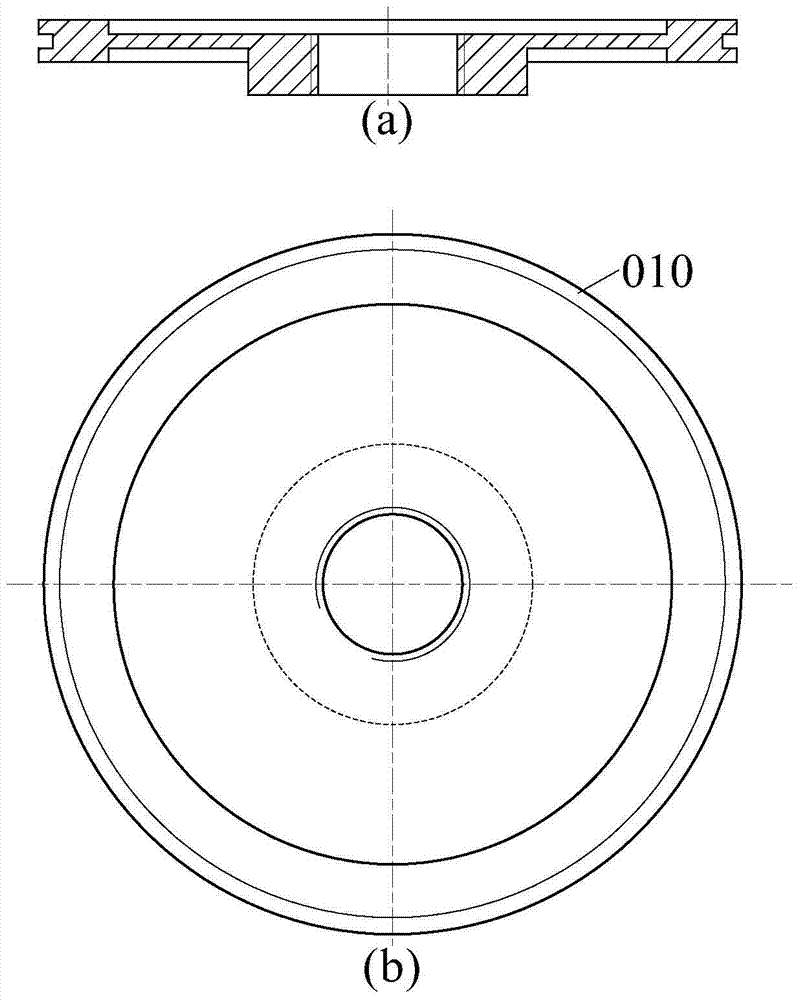
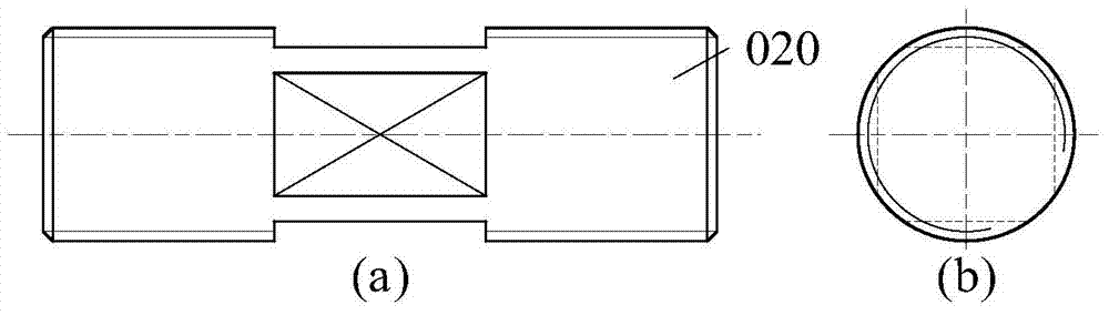
[0055] A rotating ultrasonic excitation device, see Figure 1 to Figure 10 , the rotating ultrasonic excitation device mainly includes: disc stator 010, stator support 020, lock nut 030, stator clamping device 040, piezoelectric vibrator 050, piezoelectric vibrator clamping device 060, piezoelectric vibrator locking device 070 , T-slot fastener 080 and base 090.

[0056] Wherein, the disc-shaped stator 010 is threadedly connected with the stator support 020 and locked by a locking nut 030 ; the stator clamping device 040 clamps along the edge of the disc-shaped stator 010 and is locked by the first set screw 021 . The lower end of the stator clamping device 040 is connected to the piezoelectric vibrator 050 through bolts, and the piezoelectric vibrator 050 is inserted into the piezoelectric vibrator clamping device 060 . The piezoelectric vibrator clamping device 060 is inserted into the piezoelectric vibrator locking device 070 and locked by the second set screw 071 . The p...

Embodiment 2

[0069] The embodiment of the present invention takes figure 1 The rotary ultrasonic excitation device shown is taken as an example to discuss the influence of the number of piezoelectric vibrators 050 and its topological configuration on the vibration of the disc stator 010. Figure 11 For the calculation model, the number of groups of piezoelectric vibrators 050 is P, and the number of each group is N s . The coordinate system {o, r, θ} is fixed on the disc stator 010, where the origin o is located at the geometric centroid of the disc stator 010, and the polar axis r passes through the geometric centroid of the first piezoelectric vibrator 050 in the first group , θ is the polar angle, is the ith (i=1, 2, 3,...N s ) a piezoelectric vibrator.

[0070] (1) Group symmetrical piezoelectric components

[0071] Because the piezoelectric vibrators 050 are grouped symmetrically along the circumferential direction of the disk-shaped stator 010, and the piezoelectric vibrators 0...

Embodiment 3

[0113] The embodiment of the present invention provides 6 piezoelectric vibrator excitation devices, the working wave number is 2, the grouping number P is 2, the harmonic order is 1, the space-time phase ratio is 2, and the piezoelectric vibrators 050 in the group are evenly distributed. And it works in d33 mode. Figure 12 The relationship between the angle between adjacent piezoelectric vibrators 050 and the amplitude is given. The included angle of the piezoelectric vibrator 050 in the group is π / 4, and the response of the disc stator 010 is a backward traveling wave The concrete connection process of each component in this embodiment is:

[0114](1) Connect the six piezoelectric vibrators 050 to the disk-shaped stator 010 through the stator clamping device 040; (2) insert the piezoelectric vibrators 050 into the piezoelectric vibrator clamping device 060; (3) insert the piezoelectric vibrator clamping device 060 is inserted into the piezoelectric vibrator locking devic...


PUM


Abstract

The invention discloses a rotary ultrasonic vibration excitation device and a time-space phase tuning method. The device comprises a disc stator, piezoelectric vibrators and an adjustment mechanism. The piezoelectric vibrators are installed along the axial direction of the disc stator. The disc stator and the piezoelectric vibrators are distributed along the circumference in group symmetry or uniformly. Under the action of external voltage, the piezoelectric vibrators produce axial vibration and excite periodic vibration of the disc stator. Under excitation of the multiple piezoelectric vibrators, the disc stator can produce traveling wave or standing wave. The time-space phase tuning method comprises analyzing the vibration excitation rules of the two basic configurations of the piezoelectric vibrators, namely grouped distribution and uniform distribution, and giving specific vibration excitation performance optimization technologies. The vibration excitation device has the significant advantages of high mechanical and electrical conversion efficiency, multi-time-space phase vibration excitation, dynamically adjustable amplitude, and the like. The technical problem that the existing vibration excitation device of the kind is low in efficiency and the time-space phase selection range is limited is solved.

Description

technical field [0001] The invention belongs to the field of piezoelectric drive technology, and in particular relates to a rotating piezoelectric ultrasonic excitation device and performance tuning technology whose space-time phase can be dynamically adjusted. Background technique [0002] Piezoelectric vibrators are the key components of ultrasonic motors. The inverse piezoelectric effect of the piezoelectric ceramic excites the micro-vibration in the ultrasonic frequency range, and then forms the desired microscopic vibration on the surface of the vibrator. It should be noted that existing ultrasonic vibrators usually work in a preset mode. In fact, due to the influence of processing and assembly errors, the mass and stiffness distribution of the vibrator usually change, so the working point will drift and affect the excitation efficiency. [0003] If the natural frequency splitting and mode-shape coupling phenomenon caused by structural periodicity are considered, the ...

Claims


Application Information

Patent Timeline
Patent Type & Authority Patents(China)
IPC IPC(8): H02N2/10H02N2/12H02N2/14
CPCH02N2/10H02N2/12H02N2/14
Inventor 王世宇王尧尧孙文嘉夏营赵小雪杜爱伦
Owner TIANJIN UNIV
Why Eureka
Try Eureka