Supercharge Your Innovation With Domain-Expert AI Agents!

Base plate fixing device

A technology for fixing devices and substrates, applied in ion implantation plating, metal material coating process, coating, etc., can solve problems such as fragmentation, abnormality, and crushing

Active Publication Date: 2012-07-18
AU OPTRONICS CORP
View PDF8 Cites 4 Cited by
  • Summary
  • Abstract
  • Description
  • Claims
  • Application Information

AI Technical Summary

Problems solved by technology

However, when entering the sputtering working state, the bearing seat 91 will change from a horizontal state to an upright state as shown in FIG. It may fall into the groove 99 at the lower end of the bearing seat 91 in the upright state, and the debris in the accumulation groove 99 is likely to cause the substrate 90 to be crushed during the fixing process of the subsequent substrate 90 and cause continuous fragmentation.

Method used


Image

  • Base plate fixing device
  • Base plate fixing device
  • Base plate fixing device

Examples


Embodiment Construction

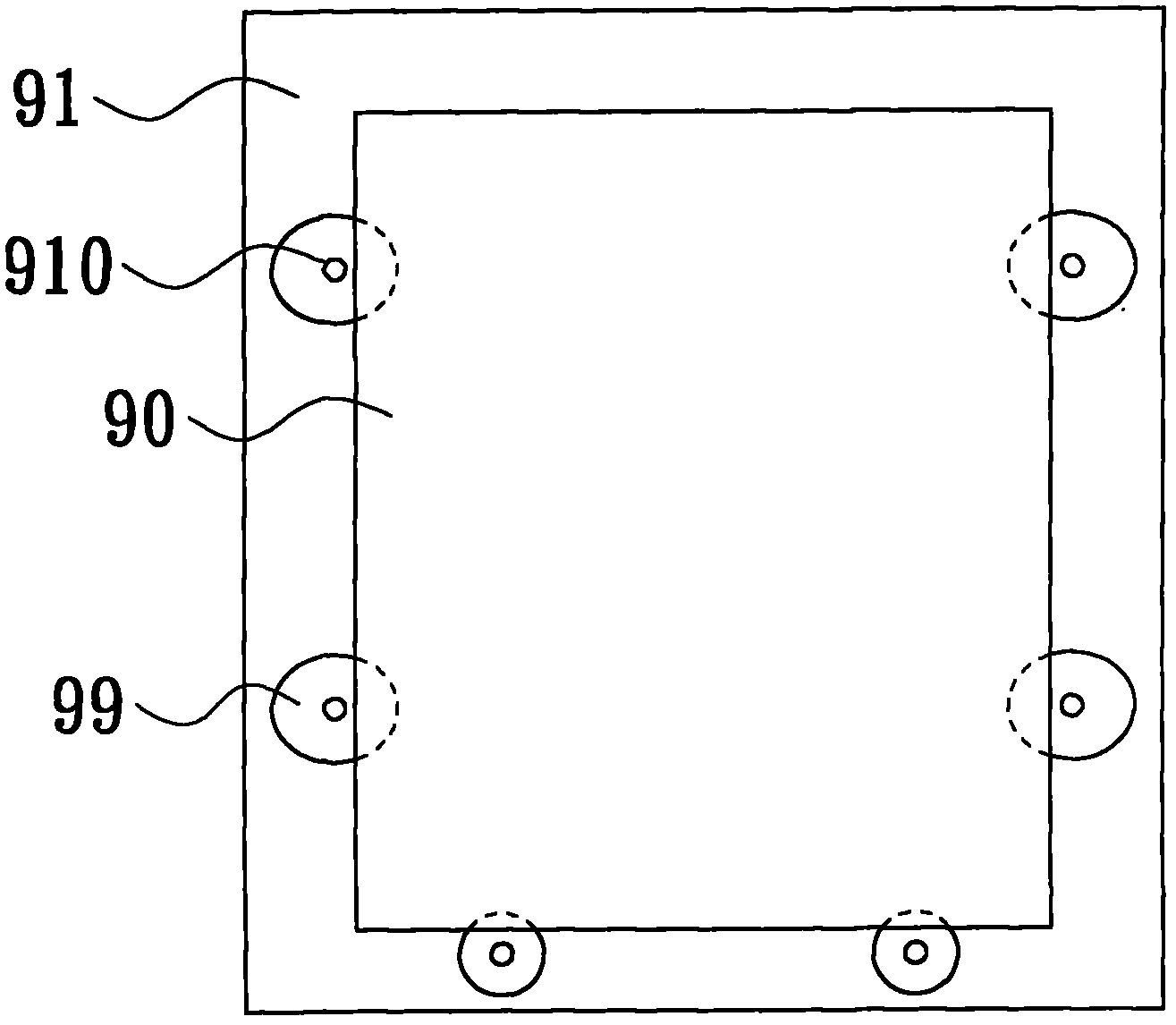
[0037] See Figure 2A-2E , is the top view and side view of the substrate fixing device developed to improve the lack of conventional devices in this case, and the Figure 2A It can be seen from the upper view in the figure that the substrate fixing device of this case uses the bearing seat 11 to carry the substrate 10, and the bearing seat 11 is larger in area than the substrate 10 and has an outer ring part 111, and there are multiple transparent parts on both sides of the outer ring part 111. The hole 110 has a groove 19 around the through hole 110 . As for the lower side of the carrier seat 11 in the figure, a contact portion 131 is provided for abutting against the substrate 10 and fixing the substrate 10 to the carrier seat 11. As for the substrate 10, it can be a glass substrate, a light-transmitting substrate or a semiconductor substrate. and other substrates.

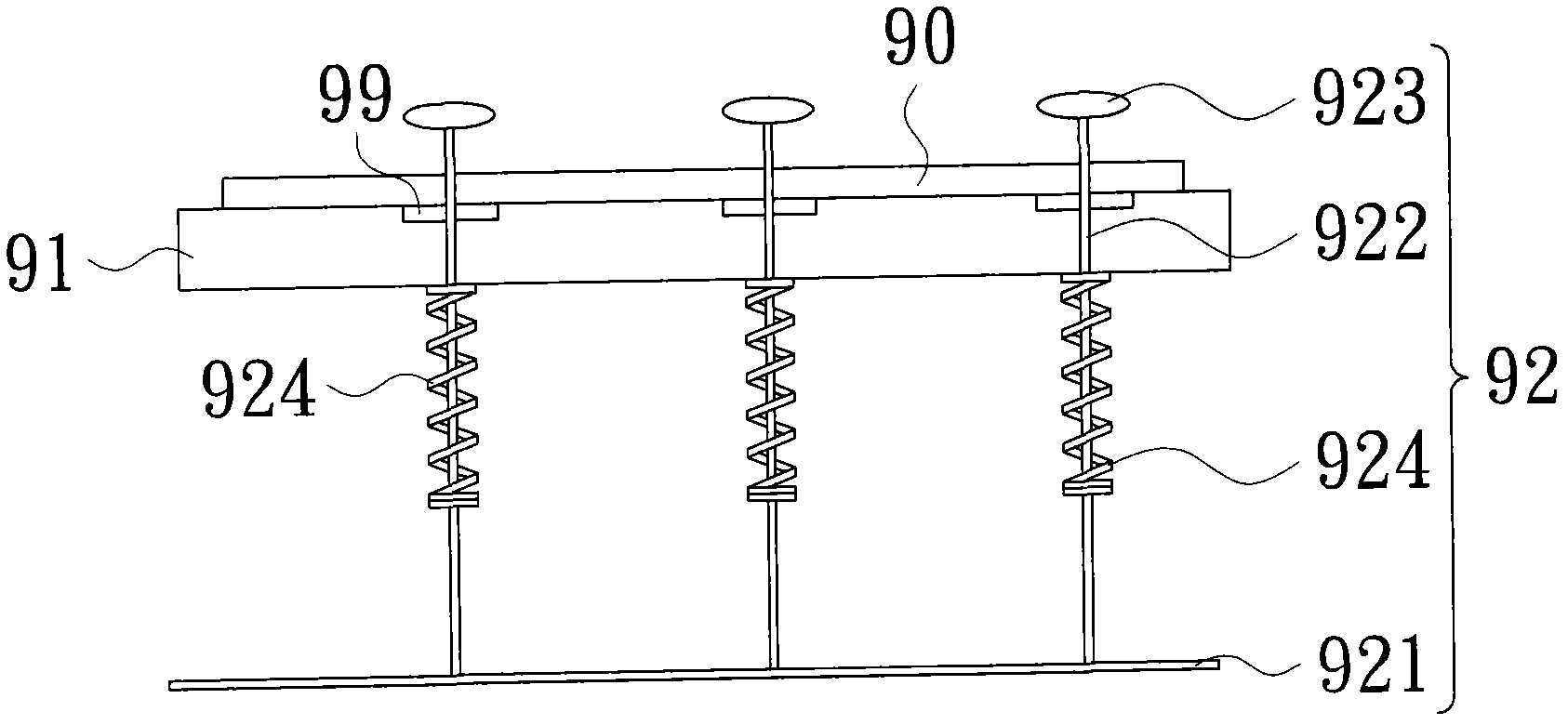
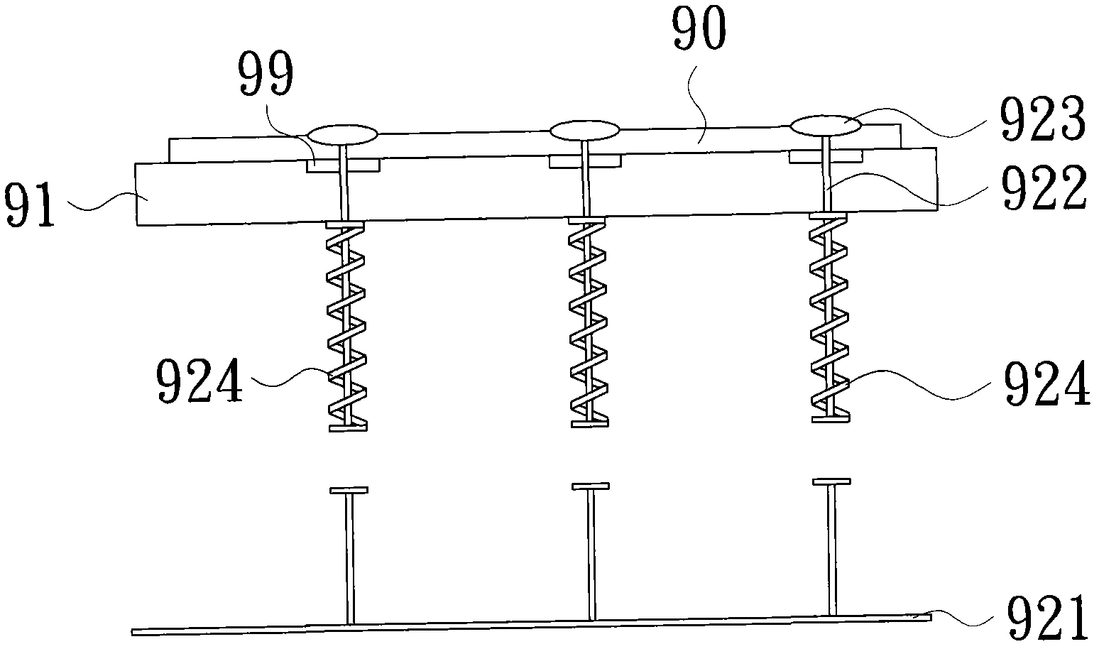
[0038] see you again Figure 2B As shown in the schematic side view, the plurality of through holes 110 i...


PUM


Abstract

The invention discloses a base plate fixing device, which is applied in the transportation of base plates. The base plate fixing device includes the components as following: a bearing seat for bearing a base plate, wherein a plurality of through holes are provided in the bearing seat; a first fixing structure, which passes through the through holes and moves along the normal direction of the base plate, wherein the base plate is supported against the bearing seat when the base plated is pressed downward; a second fixing structure, which is arranged at the first side of the bearing seat, and is connected to the bearing seat through a pulling member; and a sliding bearing structure, which is respectively fixed arranged at the bearing seat and the second fixing structure, the first convex portion of the first fixing structure moves along the normal direction to move in, thereby the second fixing structure is pushed away to release the base plate, the first convex portion of the first fixing structure moves along the normal direction to slide out, thereby the second fixing structure is pulling close to fix the base plate.

Description

technical field [0001] The present invention relates to a substrate fixing device, and in particular to a substrate fixing device in a sputtering machine. Background technique [0002] See Figure 1A ~ Figure 1D , which is a substrate fixing device in a traditional sputtering machine. The sputtering machine is widely used in various molding processes, such as thin film transistors and metal oxide semiconductor transistors. Figure 1A It shows a schematic top view of the substrate fixing device, which includes a carrier seat 91 for carrying the substrate 90 , and the carrier seat 91 has a plurality of through holes 910 and grooves 99 therein. As for Figure 1B Then it shows a schematic side view of the substrate fixing device, the plurality of through holes 910 in the bearing seat 91 are used to allow the plurality of inserts 922 of the first fixing structure 92 to pass through the through holes 910, and the gaskets 923 are respectively arranged on the through holes 910. As...

Claims


Application Information

Patent Timeline
IPC IPC(8): C23C14/50C23C14/34
Inventor 辛忠兴王培坤
Owner AU OPTRONICS CORP
Features
  • R&D
  • Intellectual Property
  • Life Sciences
  • Materials
  • Tech Scout
  • Unparalleled Data Quality
  • Higher Quality Content
  • 60% Fewer Hallucinations
Learn More