Microelectroforming machine tool

An electroforming machine tool and micro-technology, applied in the direction of electroforming, electrolysis process, etc., can solve the problems of electroforming equipment that is difficult to meet the application requirements of electroforming process, the electrode configuration mode is single and unchanged, and the process effect is not good, so as to improve the reliability Controllability and ease of operation, improve the quality of electroforming process, optimize the effect of the process environment

Inactive Publication Date: 2012-07-18
HENAN POLYTECHNIC UNIV
View PDF6 Cites 13 Cited by
  • Summary
  • Abstract
  • Description
  • Claims
  • Application Information

AI Technical Summary

Problems solved by technology

However, most of the existing micro-electroforming equipment and machine tools have a single electrode arrangement, either horizontal, vertical, or inclined, and the positions of the electrodes are fixed during electroforming, as disclosed in ZL200710019823.9 "Precise / Micro-electroforming machine tools” and “micro-electroforming devices” disclosed in ZL200810200426.6, their electrode configuration methods are single and unchanged, and it is difficult to meet the different application requirements of the electroforming process and maximize the potential of the electroforming equipment
At present, most of the operation actions such as determining the electrode position, adjusting the electrode spacing, and observing experimental phenomena of electroforming machine tools at home and abroad rely on manual operation, which is cumbersome, labor-intensive, and the process effect is not good.

Method used


Image

  • Microelectroforming machine tool
  • Microelectroforming machine tool
  • Microelectroforming machine tool

Examples


Embodiment Construction

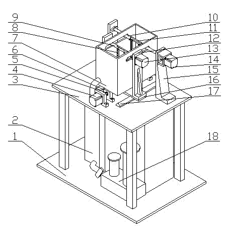
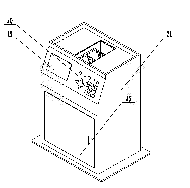
[0021] like Figures 1 to 6 As shown, the micro-electroforming machine tool includes a machine base 1, a workbench 3, an electroforming tank 7 located on the workbench 3, and an anode clamping unit and a cathode clamping unit located in the electroforming tank 7, which are located under the workbench 3 The liquid storage tank 2, the filtration circulation unit 18, the temperature control unit, the electroforming process parameter monitoring unit, in addition, the micro electroforming machine tool also includes an anode horizontal feed unit, an anode rotation unit, a cathode rotation unit and a motion control system.

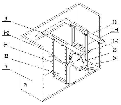
[0022] The anode clamping unit includes an anode rotating rod 9 and an anode hanger 8 installed on the anode rotating rod 9, (such as image 3 As shown) the anode hanger is formed by connecting the upper hanger 8-2 and the lower hanger 8-1 through threads, and the lower hanger 8-1 can rotate around the axis of the threaded connection relative to the upper hanger ...


PUM


Abstract

The invention discloses a microelectroforming machine tool. The microelectroforming machine tool comprises a base of the machine tool, wherein a workbench is arranged on the base, a liquid storage groove is arranged below the workbench, an electroforming groove is arranged on the workbench, an anode clamping unit and a cathode clamping unit are arranged in the electroforming groove, the anode clamping unit is used for placing an anode, a cathode clamping unit is used for placing a cathode, a filtration circulating unit connected with the liquid storage groove is arranged on the base, and the microelectroforming machine tool further comprises an anode horizontal feed unit, an anode rotating unit, a cathode rotating unit and a motion control system. The microelectroforming machine tool disclosed by the invention is compact in structure, the arrangement ways of electrodes are flexible and changeable, the motion modes of the electrodes are diverse, the operation is simple and convenient, the functions are abundant and automatic, and the microelectroforming machine tool can meet different application requirements of an electroforming process and give a full play to the potential of the electroforming device.

Description

technical field [0001] The invention belongs to the field of electroforming processing equipment, in particular to a micro electroforming machine tool. Background technique [0002] Electroforming technology based on the principle of electrodeposition is a precision forming technology with extremely high replication accuracy, and it is one of the main supporting technologies for manufacturing and processing metal micro-scale structures and parts. The micro electroforming machine tool is a necessary carrier for the implementation of the electroforming process. The configuration and layout of the cathode and anode of the electroforming machine tool, the monitoring ability of process parameters, and the overall automation of the machine tool have a great impact on the process quality, process implementation mode, and process implementation of micro electroforming parts. The ease of operation of the process has a major impact. For example, the horizontal placement of the electr...

Claims


Application Information

Patent Timeline
Patent Type & Authority Applications(China)
IPC IPC(8): C25D1/00
Inventor 明平美吕珍斌杨海柱刘伟刘洁徐锦举郑卫星
Owner HENAN POLYTECHNIC UNIV
Why Eureka
Try Eureka