

Rainwater vertical tube mounting structure for flat roof of building based on low impact development thought and mounting method
An installation method and installation structure technology, applied in the fields of environmental protection and municipal engineering, can solve the problems of increased impervious area ratio, increased flood peak flow, shortened confluence time, etc., to achieve low operation and maintenance costs, reduced pipe diameter, and reduced community flood peaks. The effect of traffic
Active Publication Date: 2012-07-18
CHONGQING UNIV +1
View PDF9 Cites 2 Cited by
- Summary
- Abstract
- Description
- Claims
- Application Information
AI Technical Summary
Problems solved by technology
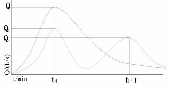
[0005] The present invention aims at the increase of impermeable area ratio, increase of runoff coefficient, and shortening of confluence time in newly built building districts in the process of urbanization, which lead to a substantial increase in flood peak f
Method used
View moreImage
Smart ImageViewing Examples

Examples
 PUM
 Abstract
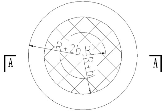
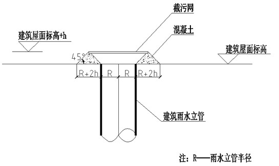
The invention discloses a rainwater vertical tube mounting structure for a flat roof of a building based on low impact development thought and a mounting method. The mounting method includes following steps: firstly, adopting a boundary of an opening of a rainwater vertical tube and the flat roof as an inner ring, pouring isosceles triangle concrete with the bottom edge of 2h and the height of h, peripherally pouring the isosceles triangle concrete around the inner ring by a circle, and taking h from a range between 5cm and 10cm; and secondly, arranging a pollutant intercepting net with the aperture ranging from 5mm to 10mm on the top of the poured annular concrete. The pollutant intercepting net can be made of plastics or anti-corrosion metal. The design method is an engineering method for a low impact rainwater development system idea, has the advantages of simple structure, low construction investment and running cost, simplicity and convenience in operation and management, high rainwater runoff peak discharge reducing ability, and plays an important role in reducing urban flood risks.
Description
Technical field [0001] The invention belongs to the technical fields of municipal engineering and environmental protection, and specifically relates to a low-impact development design method for a rainwater riser pipe on a flat roof of a building. Background technique [0002] As a precious resource, rainwater plays an important role in the urban water cycle system and the regional water environment system. Since the 1960s, with the development of the world economy, the improvement of urbanization and the increase of impervious area, the problems of the imbalance of the water circulation system and the increase of rainwater loss have become more and more serious, resulting in a series of ecological and social problems. This has become an important constraint in the process of urban sustainable development. The main manifestations are: serious rainwater runoff pollution; increased risk of urban flood disasters; serious damage to the urban ecological environment. At present, the ...
Claims
Login to View More Application Information
Patent Timeline
 IPC IPC(8): E04D13/08
Inventor柴宏祥谭松明吴鸿张甘林陈炜康威吴正松张赛
OwnerCHONGQING UNIV