Support frame and stopping structure

A technology of support frame and reset structure, applied in the field of support frame, can solve the problems of display defects, influence on display quality, impact, etc., and achieve the effect of simple and convenient operation

Inactive Publication Date: 2014-06-11
SYNCMOLD ENTERPRISE CORP
View PDF6 Cites 0 Cited by
  • Summary
  • Abstract
  • Description
  • Claims
  • Application Information

AI Technical Summary

Problems solved by technology

However, when the manufacturer packs the support frame combined with the display, if the moving part cannot be locked, the moving part is likely to move during the bumpy transportation, so that the display also moves with the moving part and hits the package materials, causing defects in the display and affecting the display quality

Method used


Image

  • Support frame and stopping structure
  • Support frame and stopping structure
  • Support frame and stopping structure

Examples


Embodiment Construction

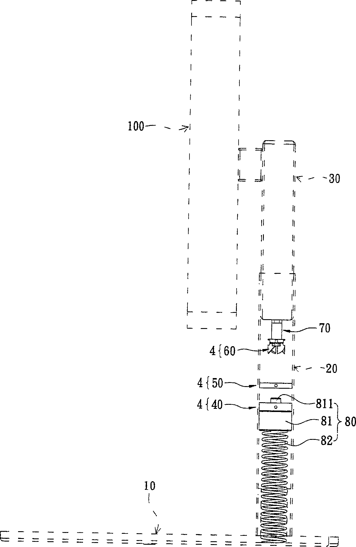
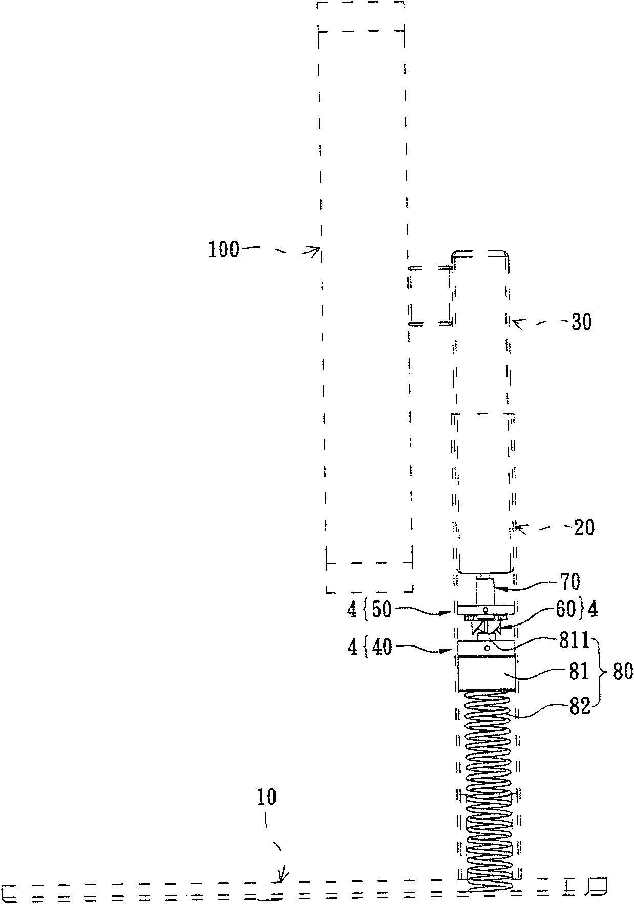
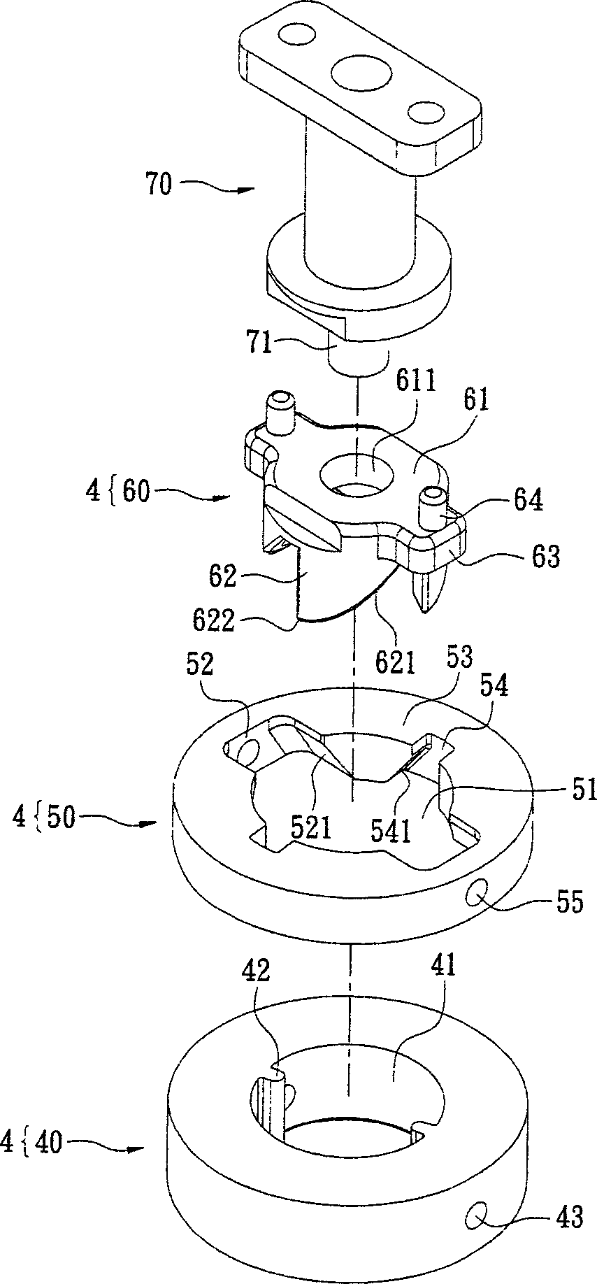
[0050] See figure 1 and figure 2 As shown, this embodiment provides a support frame, including: a base 10, a pillar 20, a moving part 30, and a latch structure 4. The pillar 20 is arranged on the base 10. The moving member 30 is disposed on the pillar 20 and can move relative to the pillar 20 along the up and down direction. The moving part 30 can be assembled on the rear side of a display 100 through other components. In addition, usually the support frame is provided with a certain force elastic member (not shown in the figure) between the pillar 20 and the moving member 30, such as a known coil-type constant force spring, to constantly apply an upward direction to the moving member 30 The force is applied so that the display 100 can move up and down relative to the pillar 20 through the movable member 30 and be positioned at a desired position. Since the structure of the above-mentioned constant-force elastic member is not the focus of the discussion in this case, it is n...


PUM


Abstract

A support frame comprises a base, a support column and a movable part, wherein the support column is arranged on the base, and the movable part is movably arranged on the support column. A stopping structure is arranged inside the support column and comprises a lower part, an upper part and a rotary part, wherein the lower part is provided with an insertion hole and two projections convexly arranged on the inner surface of the insertion hole, the upper part is positioned above the lower part in a spaced manner and provided with a circular hole, two first staggered grooves and two stoppers are arranged on the periphery of the circular hole, and the two first grooves are communicated with the circular hole. The rotary part rotates and moves vertically and comprises a body and a plurality of guide teeth, the guide teeth are formed at the lower end of the body in a surrounding manner and arranged in a uniformly spaced manner, an inclined surface is formed at the lower end of each guide tooth, and two abutting portions are convexly arranged on the periphery of the body. Therefore, the movable part can be stopped by the stopping structure.

Description

Technical field [0001] The present invention relates to a support frame, in particular to a support frame with a latch structure. Background technique [0002] The monitor is an indispensable device for displaying multimedia image data, but the monitor itself cannot stand on its own stably. Therefore, it must be combined with a support frame to stand firmly on the desktop. With the evolution of industrial technology, the structure of the support frame And functions are becoming more complex, so in addition to supporting the display firmly, the support frame must also provide a swing or rotation function for the user to adjust to the appropriate position that best meets their needs. [0003] The known support frame mainly has a base, a pillar arranged on the base, and a movable part arranged on the pillar to move up and down. The display is combined with the movable part and moves up and down relative to the pillar through the movable part, while providing a display Stable support....

Claims


Application Information

Patent Timeline
Patent Type & Authority Patents(China)
IPC IPC(8): H05K7/14F16M11/26F16B7/10
Inventor 卢德维彭琦苹张耕瑞
Owner SYNCMOLD ENTERPRISE CORP
Why Eureka
Try Eureka